
Subscribe to Our Youtube Channel
Related Manuals for Kamstrup OMNIPOWER


Summary of Contents for Kamstrup OMNIPOWER
- Page 1 Installation manual OMNIPOWER – three-phase Kamstrup A/S · Industrivej 28, Stilling · DK-8660 Skanderborg · T: +45 89 93 10 00 · info@kamstrup.com · kamstrup.com...
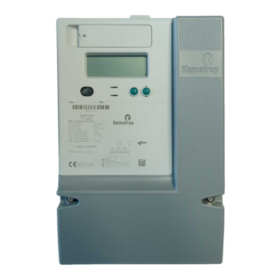
- Page 2 OMNIPOWER – three-phase Connect the meter in accordance with the installation diagram on the meter’s type label. Depending on the configuration, a fixed value is displayed, or the display changes between select- ed indications every 10 seconds. It is possible to change the display reading manually by activating the push button on the meter.
- Page 3 OMNIPOWER – three-phase The phase indications have various functions. They indicate the two situations described below. From the connection of the meter: Indications L1, L2, L3 Indicate Voltage is above minimum limit (160 V) Voltage is below minimum limit (160 V)
- Page 4 OMNIPOWER – three-phase Terminals Multi-core 7-core Massive / terminals 35 mm ≥ 6 mm ≥ 6 mm ≥ 2.5 mm Screw: Pz 2 or straight slot Torch: 2.5 – 3 Nm Load control, installation For meters with load control relay(s). Due to the delay in the meter, it is important to restart the meter (off/on) when the time is set correctly in the meter.
- Page 5 OMNIPOWER – three-phase Installation dimensions 80.3 171.7 Connection diagrams The valid connection diagram appears from the type label. 1 2 3 4 5 6 7 8 9 10 11 12 1 2 3 4 5 6 7 8 9 10 11 12...
- Page 6 OMNIPOWER – three-phase Connection diagram for modules Tilslutningsskema for moduler (DK) Connection diagram for modules (GB) Anschlussschema für Module (DE) Schéma de raccordement pour modules (FR) Tariff 1+2 Tariff 3+4 230 V 230 V 230 VAC relay output for Load Control...
- Page 7 OMNIPOWER – three-phase Kamstrup A/S • 55121316_E1_GB_10.2016...
- Page 8 OMNIPOWER – three-phase Kamstrup A/S • 55121316_E1_GB_10.2016...
Need help?
Do you have a question about the OMNIPOWER and is the answer not in the manual?
Questions and answers