Table of Contents
Advertisement
Installation and User Guide
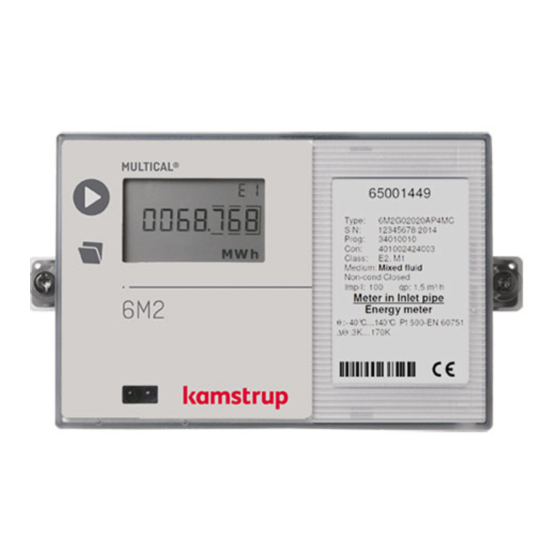
MULTICAL® 6M2
Kamstrup A/S · Industrivej 28, Stilling · DK-8660 Skanderborg · T: +45 89 93 10 00 · info@kamstrup.com · kamstrup.com
V.I.Trade s.r.o. pobočka Košice
Novozámocká 102 Čermeľská cesta 1
949 05 Nitra 040 01 Košice
vit@vit.sk kosice@vit.sk
www.vit.sk +421 915 674 492
+421 37 6513 665 +421 55 6321 321
Advertisement
Table of Contents

Related Manuals for Kamstrup MULTICAL 6M2


Summary of Contents for Kamstrup MULTICAL 6M2
- Page 1 949 05 Nitra 040 01 Košice vit@vit.sk kosice@vit.sk www.vit.sk +421 915 674 492 +421 37 6513 665 +421 55 6321 321 Kamstrup A/S · Industrivej 28, Stilling · DK-8660 Skanderborg · T: +45 89 93 10 00 · info@kamstrup.com · kamstrup.com...
- Page 2 MULTICAL® 6M2, type 6M2-H must be connected to a flow sensor with 24 V active pulse output. Irrespective of flow sensor type, “pulses/litre” must be identical in flow sensor and calculator. Battery for replacement Kamstrup type 1606064. Kamstrup A/S • 55121600_A4_GB_03.2015...
- Page 3 Installation Guide MULTICAL® 6M2 Kamstrup A/S · Industrivej 28, Stilling · DK-8660 Skanderborg · T: +45 89 93 10 00 · info@kamstrup.com · kamstrup.com...
-
Page 4: Table Of Contents
Setup via front keys 1 General information Read this guide before installing the meter. Kamstrup’s warranty obligations do not apply in case of incorrect mounting. Please note that the following installation conditions must be obeyed: - Pressure stage Kamstrup sensor pair type DS:... -
Page 5: Mounting Of Temperature Sensors
Push the plastic sleeve on the sensor cable into the sensor pocket and secure the cable by means of the enclosed M4 sealing screw. Fasten the screw with your fingers only. Seal the pockets using seal and locking wire. Kamstrup A/S • 55121600_A4_GB_03.2015... -
Page 6: Short Direct Temperature Sensor Pair
For mounting in existing installations with standard angle tees Kamstrup A/S can, furthermore, supply R½ and R¾ brass nipple fittings for the short direct sensors. Fasten the sensor’s brass unions lightly (approx. 4 Nm) using a 12 mm face wrench and seal the sensors with seal and locking wire. -
Page 7: Flow Sensor
MULTICAL® 6M2 3 Flow sensor The MULTICAL 6M2 must be used in connection with flow parts compatible with mixed fluids. Flow parts suitable for mixed fluids are e.g. mechanical and magnetic inductive. 3.1 Mounting of flow sensor A Recommended flow sensor position. -
Page 8: Gwf Flow Sensor 7
Pay attention to the direction of flow when in- stalling the meter. An arrow on the meter body indicates the direction of flow. Note: The meter should be protected against mechanical jolts or vibration, which could be present in the installation. Kamstrup A/S • 55121600_A4_GB_03.2015... -
Page 9: Mounting Of Calculator
Naturally, wall mounting is ideal when mounting in condensing environments. 52 mm 4.2 Panel mounting MULTICAL® 6M2 can be mounted direct in panels and control panels, via Kamstrup’s panel mount- ing kit, No. 66-99-104 (192 x 144 mm). Kamstrup A/S • 55121600_A4_GB_03.2015... -
Page 10: Fluid Type
The fluid type code is a 4 digit code, which states the fluid type and concentration, for which the calculator is programmed. The fluid type code can be viewed in the calcula- tor’s display (reference number 71). Kamstrup A/S • 55121600_A4_GB_03.2015... -
Page 11: Electrical Connection, Multical® 6M2
The polarity of temperature sensors T1, T2 and T3 is unimportant. Terminal no. Standard heat and cooling measurement T1 5-6 Sensor in inlet (red) T2 7-8 Sensor in outlet (blue) V1 11B-10B Flow sensor in inlet or outlet V2 79B-69B T3 51-52 Kamstrup A/S • 55121600_A4_GB_03.2015... -
Page 12: Connection Example
The active pulse output of the flow sensor is connected to the galvanically separated flow sensor input directly. This permits a cable length of up to 100 m between flow sensor and calculator. MAGFLO MULTICAL® 6M2 10B (69B) 11B (79B) Kamstrup A/S • 55121600_A4_GB_03.2015... -
Page 13: Voltage Supply Of Calculator
The battery cannot and must not be charged and must not be short-circuited for more than 2 sec. Used batteries must be handed in for approved destruction, e.g. at Kamstrup A/S. 7.2 Mains modules The modules are protection class II. They are connected by means of a two-wire cable (without ground) through the cable entry of the calculator placed in the right side of the connecting base. -
Page 14: Testing Of Function
Temperature sensor T3 outside measuring range 1…10 min. If a number of info codes appear at a time, the sum of info codes is displayed. If e.g. both tempera- ture sensors are outside measuring range, info code 12 is displayed. Kamstrup A/S • 55121600_A4_GB_03.2015... -
Page 15: Plug-In Modules
10.2.2 M-Bus, type 67-00-20 (rev. B1 or higher) M-Bus can be mounted in star, ring or bus topology. Up to 250 meter points can be connected depending on the M-Bus Master’s power supply and the total cable resistance. Kamstrup A/S • 55121600_A4_GB_03.2015... - Page 16 10.2.5 Modbus, type 67-00-67 (rev. B1 or higher) The Modbus base module for MULTICAL® 6M2 ensures simple integration from Kamstrup’s heat, cooling and water meters into a Modbus based system. The Modbus module communicates as an RTU (Remote Terminal Unit) slave device on RS-485.
-
Page 17: Setup Via Front Keys
It should be checked whether the value is valid for the reading in question. If so, the value is saved and an “OK” symbol is displayed. If not, the old value is maintained, no ”OK” symbol appears, and the display reverts to legal reading. Kamstrup A/S • 55121600_A4_GB_03.2015... - Page 18 MULTICAL® 6M2 Kamstrup A/S • 55121600_A4_GB_03.2015...
- Page 20 Kamstrup A/S • 55121600_A4_GB_03.2015...
Need help?
Do you have a question about the MULTICAL 6M2 and is the answer not in the manual?
Questions and answers