Advertisement
Advertisement

Related Manuals for Kamstrup READy Collector


Summary of Contents for Kamstrup READy Collector
- Page 1 Installation guide Kamstrup READy Collector ...
- Page 2 Copyright ® Kamstrup A/S Industrivej 28 Stilling DK‐8660 Skanderborg, Denmark All Rights Reserved The graphics and content in this document are the copyrighted work of Kamstrup and contain proprietary trademarks and trade names of Kamstrup. Third parties This document may contain links to other parties. Kamstrup makes no warranty or representation regarding any linked information appearing therein. Such links do not constitute an endorsement by Kamstrup of any such information and are provided only as a convenience. Kamstrup is not responsi‐ ble for the content or links displayed by third parties. Industrivej 28, Stilling ∙ 8660 Skanderborg ∙ Denmark ∙ Tel: +45 89 93 10 00 ∙ Fax: +45 89 93 10 01 ∙ info@kamstrup.com ∙ www.kamstrup.com Kamstrup A/S ∙ Manual ID (DocProperty ManualID)_INITIALS (DocProperty ManualINITIALS) 2/12 ...
-
Page 3: Table Of Contents
Kamstrup READy Collector Contents 1. FCC Caution 4 2. Symbols used in this document 5 3. Installing the READy Collector top 6 4. Connecting the READy Collector Top. 9 5. Installing the antennas 10 6. Maximum ERP 11 7. Troubleshooting 12 Kamstrup A/S ∙ Manual ID (DocProperty ManualID)_INITIALS (DocProperty ManualINITIALS) 3/12 ... -
Page 4: Fcc Caution
Kamstrup READy Collector FCC Caution This equipment has been tested and found to comply with the limits for a Class B digital device, pursuant to part 15 of the FCC Rules. These limits are designed to provide reasonable protection against harmful interference in a residential installation. This equipment generates, uses and can radiate radio frequency energy and, if not installed and used in accordance with the instructions, may cause harmful interference to radio communications. However, there is no guarantee that in‐ terference will not occur in a particular installation. If this equipment does cause harmful interfer‐ ence to radio or television reception, which can be determined by turning the equipment off and on, the user is encouraged to try to correct the interference by one or more of the following measures: Reorient or relocate the receiving antenna. Increase the separation between the equipment and receiver. Connect the equipment into an outlet on a circuit different from that to which the receiver is connected. Consult the dealer or Kamstrup directly. Kamstrup A/S ∙ Manual ID (DocProperty ManualID)_INITIALS (DocProperty ManualINITIALS) 4/12 ... -
Page 5: Symbols Used In This Document
Kamstrup READy Collector Symbols used in this document Warning indicates a potentially hazardous situation, which if not avoided, could result in death or serious injury. Caution indicates a situation, which if not avoided, could result in damage to equipment, mild injury, damage to software, loss of data or invalid results. Notes important information, ex. Pre conditions, necessary steps before proceeding etc. Kamstrup A/S ∙ Manual ID (DocProperty ManualID)_INITIALS (DocProperty ManualINITIALS) 5/12 ... -
Page 6: Installing The Ready Collector Top
Kamstrup READy Collector Installing the READy Collector top NOTE: Only authorized personnel is allowed to perform an installation of this system. ‐‐‐ To install the Top box, use the small adaptor plate and the bracket illustrated below: For installation on a wall, use the following plug and screws. For installation on a pipe, use stainless steel clamps. (Not included) Bolt the bracket and adaptor plate together using the screws located near the middle of the plate. Install the assembly on the READy Collector top. The box needs to be open in order to perform the installation. Use the bolts installed on the adaptor plate. NOTE: The cable openings must face down when installing the final product. Kamstrup A/S ∙ Manual ID (DocProperty ManualID)_INITIALS (DocProperty ManualINITIALS) 6/12 ... - Page 7 Kamstrup READy Collector The result should look similar to this. When closing the lid again, ensure the sealing is intact. Tighten the nuts in a cross pattern to even out the pressure on the sealing. Kamstrup A/S ∙ Manual ID (DocProperty ManualID)_INITIALS (DocProperty ManualINITIALS) 7/12 ...
- Page 8 Kamstrup READy Collector To install the bracket on a wall, Disassemble the bracket into two, by removing these bolts. Install the bracket onto the wall using the following screws and plugs. Or install the bracket on a pipe, using stainless steel clamps. (Optional). Kamstrup A/S ∙ Manual ID (DocProperty ManualID)_INITIALS (DocProperty ManualINITIALS) 8/12 ...
-
Page 9: Connecting The Ready Collector Top
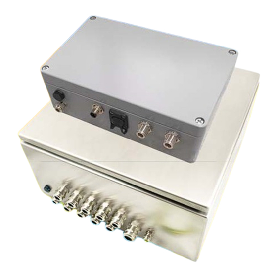
Kamstrup READy Collector Connecting the READy Collector Top. Use a 24V DC power supply, capable of delivering a peak effect of 40W. Make sure the cables are connected correctly. Note: the small marking in the power supply end. Cable end label says: “0” for negative connection (0 VDC) “1” for possitive connection (24VDC) Connect a LAN cable to grant the READy Collector Top access to the internet and access to Kamstrup systems. Power RF1 RF2 Ground Ethernet Connect the Ground wire to a solid ground accessible near the installation site. ... -
Page 10: Installing The Antennas
Kamstrup READy Collector Installing the antennas When installing the antennas, ensure you keep at least the minimum distance between the anten‐ nas: Minimum distance between the antennas: 30 inches Use the Antenna beam (5000 474) and Brackets (5000 475). Install the Bracket on the beam Install the beam on the pole or mast The antennas comes with brackets from manufacture; use these in according to the next step. Install the antennas with the correct distance. (Min. 30 inches) Example of installation: Connect the RF Cable to antenna 1 and RF1 on the READy Collector Top. Connect the RF Cable to antenna 2 and RF2 on the READy Collector Top. RF1 RF2 This concludes the setup of the READy Collector Top. Kamstrup A/S ∙ Manual ID (DocProperty ManualID)_INITIALS (DocProperty ManualINITIALS) 10/12 ... -
Page 11: Maximum Erp
Kamstrup READy Collector Maximum ERP Caution: Before starting work on the antennas, turn off the power to the system. Kamstrup US AMI solution use Data Collectors to collect data from meters and end‐devices. The data is sent on an uplink frequency and received by the collector. Based on decisions made by the READy head end system, the collector acknowledge the reception of the data by transmitting back to the meter or end‐device using the downlink frequency. The data collector is capable of transmitting up to 5 Watt output power, which is amplified by the gain in the antenna used on the data collector site (if antenna gain is >0dBi). Based on the radio propagation study, a data collector site is tailored to fit the needs. The antenna is selected (amplifies the signal) and the antenna cable and length is selected (loss – attenuation on the signal). The transmitter must at no time transmit higher than the allowed maximum output power (meas‐ ured at the antenna connector of the data collector top box) and it must at no time radiate more power (ERP) than the granted license specify. WARNING The maximum output power in W dictates the maximum output power a data collector can transmit with and it is adjustable in READy up to the specified maximum. If the selected antenna have a gain which result in a higher radiated power (ERP) than allowed by the license, the maximum output power in W filled in the Frequency License service must be decreased accordingly! Max ERP – antenna gain + cable loss = max output power (if lower or equal to FCC license max.) The calculation must be made by Kamstrup based on the selected antenna and cable for the data collector site. Kamstrup A/S ∙ Manual ID (DocProperty ManualID)_INITIALS (DocProperty ManualINITIALS) 11/12 ... -
Page 12: Troubleshooting
Kamstrup READy Collector Troubleshooting Power cable not installed correctly: 1. Check there is activity on the Ethernet port to the READy Collector Top Collector not visible in LSR tool: Faulty connection in the READy Collector Base Power cable not installed correctly: 2. Check there is activity on the Ethernet port to the READy Collector Top 3. Check there is power to the READy Collector Top Collector not visible in READy Manager. 4. Check there is activity on the Ethernet port to the READy Collector Top 5. Check there is activity on the Ethernet port for outgoing data. 6. If using a SIERRA Wireless modem, check the data activity LED. No cellular connection 7. Check the GSM antenna is plugged in the right channel “Cellular”. 8. For further trouble shooting on the modem, go to the service guide. No wired internet connection/no activity on LAN port. 9. Check all connections in the READy Collector Base. 10. Test the connection on a pc. If no connection, contact you network provider. No data visible in READy Manager 11. Check if the frequency service is setup. 12. Perform an installation frame (at the meter site) ...
Need help?
Do you have a question about the READy Collector and is the answer not in the manual?
Questions and answers