
Related Manuals for Kamstrup OMNIPOWER


Summary of Contents for Kamstrup OMNIPOWER
- Page 1 Installation manual OMNIPOWER – single-phase Kamstrup A/S · Industrivej 28, Stilling · DK-8660 Skanderborg · T: +45 89 93 10 00 · info@kamstrup.com · kamstrup.com...
- Page 2 OMNIPOWER – single-phase Installation manual Connect the meter in accordance with the installation diagram on the meter’s type label. Depending on the configuration, a fixed value is displayed, or the display changes be- tween selected indications every 10 seconds. It is possible to change the display reading manually by activating the push button on the meter.
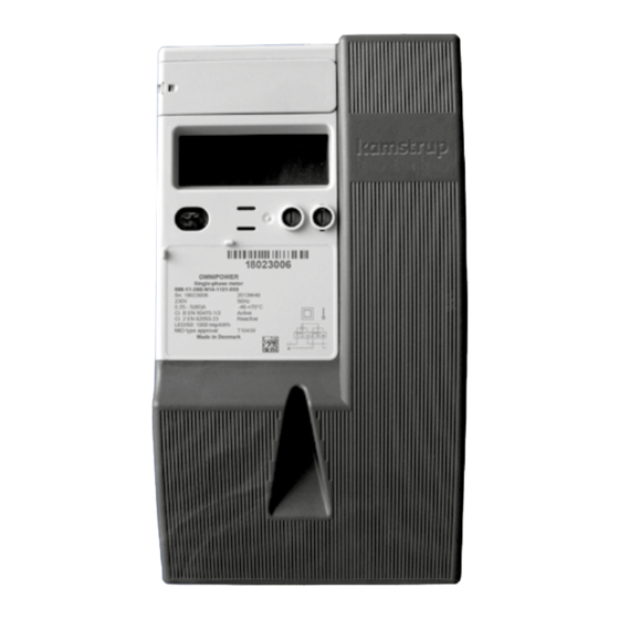
- Page 3 OMNIPOWER – single-phase Installation manual Secondary module LCD display Optical interface LED (meter constant) LED breaker status (only meters with internal breaker) Push button Sealable push button Type label Utility seals The meter constant LED blinks proportionally to the consumed active energy.
- Page 4 OMNIPOWER – single-phase Installation manual The phase indications have various functions. They indicate the two situations described below. From the connection of the meter: Indications Indicate Voltage is above minimum limit (160V)) Voltage is below minimum limit (160V) Indications Indicate Load is above minimum limit (2.3W)
- Page 5 Mounting a communication module in the meter may influence the radio communica- tion. Please contact Kamstrup A/S. With disconnect function With this type of meter, it must be checked that the red diode is switched off. This indi- cates that the consumer’s supply is disconnected.
- Page 6 OMNIPOWER – single-phase Installation manual Installation dimensions OMNIPOWER OMNIPOWER ST 81.6 81,6 81.6 81,6 81,6 81,6 81,6 81,6 81,6 81.6 81.6 81,6 128.7 128,7 128,7 128,7 128,7 128.7 Connection diagrams The valid connection diagram appears from the type label. OMNIPOWER...
- Page 7 OMNIPOWER – single-phase Connection diagram for modules Tilslutningsskema for moduler (DK) Connection diagram for modules (GB) Anschlussschema für Module (DE) Schéma de raccordement pour modules (FR) Tariff 1+2 Tariff 3+4 230 V 230 V 230 VAC relay output for Load Control...
- Page 8 OMNIPOWER – single-phase Kamstrup A/S • 55121312_E1_GB_09.2015...
Need help?
Do you have a question about the OMNIPOWER and is the answer not in the manual?
Questions and answers