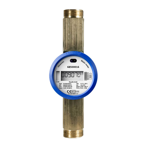
Kamstrup flowIQ 3100 Technical Description
Water meter
Hide thumbs
Also See for flowIQ 3100:
- Technical description (30 pages) ,
- Tecnical description (52 pages) ,
- Technical description (68 pages)
Table of Contents
Advertisement
Advertisement
Table of Contents

Related Manuals for Kamstrup flowIQ 3100


Summary of Contents for Kamstrup flowIQ 3100
- Page 1 Technical Description flowIQ® 3100 Water Meter...
- Page 2 TECHNICAL DESCRIPTION flowIQ® 3100 Ka st up A/S • Te h i al Des iptio • 5512-1242_D _GB • 09.2016...
-
Page 3: Table Of Contents
flowIQ® 3100 TECHNICAL DESCRIPTION Contents ......................... 5 General description Front Plate ............................... 6 Sealing ..............................6 ..........................7 Approval Technical data ........................7 Mechanical data ............................7 Electrical data ............................8 Materials ..............................8 Water Meter types ........................... 9 Measurement Accuracy .......................... 10 Temperature measurement ........................ - Page 4 14.3 Data content ............................55 14.1 Encryption ............................. 55 ......................55 Communication (KMP) 15.1 Optical eye activation ..........................55 METERTOOL for Kamstrup Water Meters ................55 .......................... 56 Approvals 17.1 Type approvals ............................56 17.2 Measuring Instrument Directive (MID) ..................... 56 ........................
-
Page 5: General Description
MULTICAL® 21 household meters. The water meter can and must only be opened by Kamstrup A/S. If the meter has been opened and the sealing has thus been broken, the meter is no longer valid for billing purposes. Furthermore, the factory guarantee no longer applies. -
Page 6: Front Plate
TECHNICAL DESCRIPTION flowIQ® 3100 1.1 Front Plate Meter information in permanent laser engraved text. ealing The meter is sealed diagonally as shown Security seal (sealing ring) Ka st up A/S • Te h i al Des iptio • 5512-1242_D _GB • 09.2016... -
Page 7: Approval
OIML R49 with the with FO‘CE Certifi atio as notified body. Directive (MID) based on OIML: I te atio al O ga izatio of Legal Met olog Please contact Kamstrup A/S for further details on national approvals and verification. Approval cert no. DK-0200-MI001-017... -
Page 8: Electrical Data
TECHNICAL DESCRIPTION flowIQ® 3100 3.2 Electrical data Battery 3.65 VDC, one C-cell lithium Battery lifetime up to 16 years at tBAT < 30 °C up to 8 years at tBAT < 55 °C EMC data (OIML) Fulfil MID class E1 and E2 (Electromagnetic class) 3.3 Materials Wetted parts... -
Page 9: Water Meter Types
flowIQ® 3100 TECHNICAL DESCRIPTION 3.4 Water Meter types ) – see table below. Combinations of connection type, meter size, overall length and nominal flow (Q Nom. Min. Max. Dynamic Min. Max. Pressure Connec- Length Non- Temp. loss flow flow flow range cut off tion on... -
Page 10: Measurement Accuracy
: Permanent/nom. flow : Overload/max. flow (1.25xQ OIML R49 requirements to water meters MPE (maximum permissible error range – according to OIML R49) Kamstrup water meter flowIQ® 3100 measuring accuracy R100 1.000 10.000 Flow l/h Ka st up A/S • Te h i al Des iptio • 5512-1242_D _GB • 09.2016... -
Page 11: Temperature Measurement
flowIQ® 3100 TECHNICAL DESCRIPTION 3.6 Temperature measurement flowIQ® 3100 measures water and ambient/meter temperature - also see section Data function: Measuring temperature The following accuracies apply to temperature data: Water temperature: 0 - 20 °C ± 1 °C 20 - 30 °C ± 2.5 °C >... -
Page 12: Type Overview
TECHNICAL DESCRIPTION flowIQ® 3100 Type overview Type 031- Communication Wireless M-Bus, 868 MHz, mode C1 – ver. 2 Wireless M-Bus, 868 MHz, mode T1 – OMS – ver. 2 Wired M-Bus Supply ea s atte life, C-cell Meter size [m³/h] Connection Length [mm] Dynamic range... -
Page 13: Configuration
Encryption level No encryption Utility encryption (only available for selected markets) Encryption with separately forwarded key Unless otherwise stated in the order, Kamstrup supplies the following: Ka st up A/S • Te h i al Des iptio • 5512-1242_D1_GB • 09.2016... -
Page 14: Dimensioned Sketches
TECHNICAL DESCRIPTION flowIQ® 3100 6 Dimensioned sketches Type: 1.6 m³/h – G¾B (R½) x 110 mm 2.5 m³/h – G¾B (R½) x 110 mm 2.5 m³/h – G1B (R¾) x 190 mm /h – G5/4B (R1) x 175 mm 2.5 m /h –... - Page 15 flowIQ® 3100 TECHNICAL DESCRIPTION 16 m³/h – DN50 x 270 mm L = 270 25 m³/h – DN65 x 300 mm 40 m³/h – DN80 x 300 mm Ka st up A/S • Te h i al Des iptio • 5512-1242_D1_GB • 09.2016...
-
Page 16: Dimensions
TECHNICAL DESCRIPTION flowIQ® 3100 6.1 Dimensions 6.1.1 Thead ISO 228-1 6.1.2 Flange DN Water meter, Type L – 16m Water meter, Type M – 25m Ka st up A/S • Te h i al Des iptio • 5512-1242_D _GB • 09.2016... -
Page 17: Meter Size, Connection, Weight And Dimensions
flowIQ® 3100 TECHNICAL DESCRIPTION Water meter, Type N / E– 40 / 100 m 6.2 Meter size, connection, weight and dimensions See dimensions for threaded and flanged meters in the table below: Approx. Thread/flange weight Meter type m³/h mm mm mm... -
Page 18: Pressure Loss
TECHNICAL DESCRIPTION flowIQ® 3100 7 Pressure loss According to OIML R49 maximum pressure loss must not exceed 0.63 bar (0.063 MPa) in range Q to Q The pressure loss in a meter increases with the square of the flow and can be stated as: ... -
Page 19: Installation
PN10 or PN16 connections are used. Kamstrup A/S recommends drinking water approved fibre gaskets for cold water installations. If a non-return valve is installed, it will usually be necessary to use 4 mm PE gaskets instead, to prevent the collar of the coupling from damaging the valve. -
Page 20: Installation Angle
TECHNICAL DESCRIPTION flowIQ® 3100 8.1.1 Installation conditions As mentioned above the use of new gaskets in original quality is of crucial importance. The sealing surface of the threaded connection must be clean and level ALWAYS use new gaskets 8.1.2 Permissible operating conditions …... -
Page 21: Straight Inlet
flowIQ® 3100 TECHNICAL DESCRIPTION Straight inlet The meter requires neither straight inlet nor straight outlet to meet the Measuring Instruments Directive (MID) 2004/22/EC and OIML R49. A straight inlet section will only be necessary in case of heavy flow disturbances before the meter. Recommended water meter position Recommended... -
Page 22: Reading And Data
Receiving the Wireless M-bus signal, which is emitted at intervals of 16 or 96 seconds, depending on the meter configuration, alternatively receiving the wired M-Bus datagram. • Reading via the optical eye, e.g. by means of Kamstrup A/S wireless optical reading head, or optical reading head with USB connector. 9.2 Volume measurement The meter calculates water flow currently according to a fixed measuring cycle. -
Page 23: Data Function: Maximum Flow And Minimum Flow
flowIQ® 3100 TECHNICAL DESCRIPTION 9.4 Data function: Maximum flow and minimum flow flowIQ® 3100 registers maximum and minimum flow on a daily as well as monthly basis. Maximum and minimum flow are calculated as the largest and the smallest value respectively of a number of current flow measurements. -
Page 24: Optional Register In Data Logger
TECHNICAL DESCRIPTION flowIQ® 3100 Temperature measurement 9.5.2 Ambient/meter temperature Monitoring ambient/meter temperature in the installation can be used for warnings of freezing or unintended high temperatures. The measurements of the meter temperature are made inside the meter housing, which corresponds to the ambient temperature in the environment where the meter is installed. The temperature is measured every minute. - Page 25 flowIQ® 3100 TECHNICAL DESCRIPTION Only valid for meter sizes 1.6, 2.5 and 4.0 m Ka st up A/S • Te h i al Des iptio • 5512-1242_D1_GB • 09.2016...
-
Page 26: Display Functions
TECHNICAL DESCRIPTION flowIQ® 3100 9.7 Display functions flowIQ® 3100 is fitted with an easily readable LCD-display including 8 digits, measuring units, information field with info codes as well as flow indicator (arrows). The display layout is shown in the figure below. In the following examples white/uncoloured segments (see below) indicate inactive segments, whereas black segments indicate active segments. - Page 27 flowIQ® 3100 TECHNICAL DESCRIPTION Below you see an example of volume reading in normal mode showing V1 = 03,745.214 m Below you see an example of volume reading in verification mode showing V1HighRes = 45,214.698 L 9.7.2 Resolution The resolution of the display can be varied by changing the number of visible decimals after the point. This change has no influence on the measurement itself.
- Page 28 TECHNICAL DESCRIPTION flowIQ® 3100 9.7.4 Info codes The info codes consist of 7 separate text signs (framed in the above sketch), which indicate a special condition in the meter. The signs flash when active. If not, they are OFF. The individual info codes are described below: Info code - ERROR This info code is not used.
- Page 29 flowIQ® 3100 TECHNICAL DESCRIPTION Info code - BURST This info code is activated if the flow exceeds a given value for a continuous period of 30 minutes. This can be a sign of a burst in the pipe installation which requires prompt action. The size of the 30-minute flow (which prompts the info code BURST) can be determined by the customer when submitting the order, and later by Metertool.
- Page 30 Info code – RADIO OFF (transport mode) This info code is active in the display when the water meter leaves Kamstrup A/S, and indicates, that the ete is still i t a spo t ode a d that the uilt-in Wireless M-Bus radio transmitter has not yet been activated.
- Page 31 flowIQ® 3100 TECHNICAL DESCRIPTION 9.7.5 Adjustment mark The s ol A and the corresponding figure indicate the number of flow adjustments and legal changes after factory verification. For further description see paragraph Legal changes outside seal It is possible to reset the legal registers and change the factory programmed flow curve to a limited extent. The flow adjustment makes it possible to adjust the existing curve at three points.
-
Page 32: Wireless M-Bus
TECHNICAL DESCRIPTION flowIQ® 3100 9.7.6 Flow arrows The flow arrows in the left side of the display indicate whether water flows through the meter (in the right direction). If there is no flow (or backwards flow), all arrows are OFF. If there is flow through the meter, the following sequence runs with a timing of 0.5 seconds per reading. - Page 33 If the meter is configured for Wireless M-Bus mode T1 OMS, data transmission will only take place every 15 minutes – four times per hour. Kamstrup does not offer reading devices for Wireles M-Bus mode T1 OMS. Ka st up A/S • Te h i al Des iptio • 5512-1242_D1_GB • 09.2016...
-
Page 34: Wired M-Bus Version Of Flowiq® 3100
TECHNICAL DESCRIPTION flowIQ® 3100 9.9 Wired M-Bus version of flowIQ® 3100 9.9.1 For billing and analysis Fixed datagram Up to 9600 baud communication speed Primary/secondary/enhanced secondary addressing According to M-Bus standard EN 13757:2013 9.9.2 Introduction flowIQ® 3100 is available with wired M-Bus offering easy reading of the water meter via, for example, an M-Bus Master. - Page 35 flowIQ® 3100 TECHNICAL DESCRIPTION 9.9.12 Communication speed The meter supports 300, 2400 and 9600 baud communication speed and automatically detects the communication speed used by the M-Bus master. 9.9.13 Communication interval Reading intervals ≥ one minute may not reduce the battery lifetime of the meter at any communication speed.
- Page 36 TECHNICAL DESCRIPTION flowIQ® 3100 9.9.17 Technical specifications Physical Fully integrated M-Bus interface Communication Readout speed 300/2400/9600 baud with automatically speed detection Communication interval Longer than 1 minute (recommended) Protocol EN 13757:2013 Configuration METERTOOL HCW via optical read-out head Power consumption 1 unit load (1.5 mA) per M-Bus slave 422 Ω/0.5 nF Rin / Cin...
-
Page 37: Optical Eye
The meter is fitted with an optical eye that gives access to the meter's external interface, with which all the meter's data registers can be read. For instance data can be read using Kamstrup's optical reading head. The reading head includes a permanent magnet which switches on the optical eye. The interface communicates at 1200 baud. -
Page 38: Data Loggers
TECHNICAL DESCRIPTION flowIQ® 3100 10 Data loggers 10.1 Memory flowIQ® 3100 has a permanent memory (EEPROM), in which the values of various data loggers are saved. Loggers are read through the optical eye. The meter includes the following registers: Data logging interval Data logging depth Logged value Monthly logger... -
Page 39: Monthly And Daily Loggers
flowIQ® 3100 TECHNICAL DESCRIPTION 10.2 Monthly and daily loggers The table below shows which registers are logged on the first day of the month, and which are logged every day. The daily logger is an absolute log, i.e. current meter reading is logged every day. Monthly logger Daily logger Register type... -
Page 40: Info Register
TECHNICAL DESCRIPTION flowIQ® 3100 10.4 Info register Every time the information code changes, date and info code are logged. Thus, it is possible to data read the latest 50 changes of the information code as well as the date the change was made. Reading is only possible via the optical eye. - Page 41 flowIQ® 3100 TECHNICAL DESCRIPTION Every time an info code has been active, it is logged together with an indication of how long the info code has been active. The time indication informs with coarse resolution, how many hours the corresponding info code has been active within the latest 30 +1 days, i.e.
-
Page 42: Meter Modes (Settings)
TECHNICAL DESCRIPTION flowIQ® 3100 10.5 Meter modes (settings) The water meter has 2 modes: Meter mode: Normal Verification Measuring cycle 4 s/32 s 0.5 s/4 s (measurement/calculation) Display value Display dots, frequency 1 Hz 2 Hz Mode, time out Verification mode is only used by authorised laboratories during verification. 10.6 Normal mode Normal mode is meant for normal operation. - Page 43 The meter is initially verified from the factory. A new factory adjustment requires disassembling of the meter and can only be carried out by Kamstrup A/S. When the meter has been locked it is only possible to make a percentage correction of the flow curve at three individual points. This is called re-adjustment.
-
Page 44: Measuring Principle
Flow sensor manufacturers have been working on alternative techniques to replace the mechanical principle. Research and development at Kamstrup has proven that ultrasonic measuring is the most viable solution. Based on microprocessor technology and piezo ceramics, ultrasonic measuring is not only accurate but also reliable. - Page 45 flowIQ® 3100 TECHNICAL DESCRIPTION In principle, flow is determined by measuring the flow velocity and multiplying it by the area of the measuring pipe: where: Q is the flow is the flow velocity is the area of the measuring pipe The area and the length which the signal travels in the sensor are well-known factors.
-
Page 46: Calculation Of Flow Volume
TECHNICAL DESCRIPTION flowIQ® 3100 11.4 Calculation of flow volume The measurement of the actual velocity of sound in water is also used to determine the temperature of the water, as there is a correlation between these two values, at temperatures below approx. 30 °C The flow is calculated, as mentioned above, by multiplying the flow rate and the cross-sectional area: ... -
Page 47: Signal Paths
flowIQ® 3100 TECHNICAL DESCRIPTION 11.5 Signal paths : 1. … ³/h Triangle The sound path covers the measuring tube in a triangle. Ultrasound signals are sent from the transducers through the measuring tube via reflectors. 11.5.1 Measuring sequences During flow measuring, the meter passes through a number of sequences, repeated at fixed intervals. Deviations only occur when the meter is in test mode. -
Page 48: Pulse Adapter For Flowiq® 3100
TECHNICAL DESCRIPTION flowIQ® 3100 12 Pulse Adapter for flowIQ® 3100 The Pulse Adapter is a stand-alone unit designed to be mounted on the flowIQ® 3100 water meter. The unit must be mounted indoors in utility rooms or similar. The Pulse Adapter receives optical pulses from flowIQ® 3100 and transmits them to external data acquisition or control systems through a wired pulse output. -
Page 49: Application - Environment
flowIQ® 3100 TECHNICAL DESCRIPTION Application – environment 12.2 ie t te pe atu e: °C… °C °C… °C Storage temperature: - Protection class: IP65 12.3 Lifetime 16 years, with a single AA battery Battery change is possible 12.4 Connection of Pulse Adapter From the factory the meter is configured not to transmit optical pulses –... -
Page 50: Pull-Up
TECHNICAL DESCRIPTION flowIQ® 3100 As soon as the button is activated, serial optical communication between Pulse Adapter and meter starts. If the set up is su essful, PULSE ON is displa ed fo fi e se o ds as sho a d the LED o the u it remains ON for three seconds –... - Page 51 flowIQ® 3100 TECHNICAL DESCRIPTION TB1 pin 1 "+" 10ohm TB1 pin 2 "-" Simplified diagram for Pulse Adapter output 12.5.1 Description Pulse output: Type Open Drain Maximum input voltage Maximum current sink 27mA Vout < 0.3V @ 0.1mA current On voltage Vout <...
-
Page 52: 3100 / Multical® 21
TECHNICAL DESCRIPTION flowIQ® 3100 13 Pulse Interface for flowIQ® 3100 / MULTICAL® 21 Pulse Interface, type 66-99-143, is used during calibration and verification in test stands with pulse interface. The optical reading head is retained on flowIQ® 3100 by means of a transparent plastic holder (Optical support, type 6561-331). -
Page 53: Connection Pulse Interface
flowIQ® 3100 TECHNICAL DESCRIPTION 13.1 Connection Pulse Interface The pulse interface has two outputs – Volume and Energy . flowIQ® 3100 only uses the volume output. Each pulse output consists of 3 terminals: GND , Volume Pulse and Pull-up Volume . When the pulse output is a ti e, Pulse is d a to GND, i.e. -
Page 54: Data Communication
‘adio t a s issio has ee i te upted if ‘ADIO OFF is displa ed. RADIO OFF is activated at the end of the production process at Kamstrup A/S. The meter removes RADIO OFF automatically, when the volume register has counted water consumption for approx. 5 seconds. -
Page 55: Data Content
3100 can be ordered without or with encryption of data transmission. If encryption of data is selected, it consists of 128 bit AES counter mode encryption. Kamstrup A/S recommends encryption. Meters produced for Russia will always be WITHOUT encryption. -
Page 56: Approvals
The meter has been MID approved on the basis of OIML R49-1 and R49-2 with FORCE Certification as notified body. Please contact Kamstrup A/S for further details on type approvals and verification. 17.2 Measuring Instrument Directive (MID) flowIQ® 3100 is available with CE-marking according to MID (2004/22/EC). The certificates have the following... -
Page 57: Troubleshooting
The meter housing is hermetically closed and any repair requires that the sealing is broken. Therefore, repairs including battery replacement must be carried out by Kamstrup A/S. Should you, however, experience an operating problem with the meter, the table below can be used for troubleshooting. -
Page 58: Disposal
Ka st up A/S Kamstrup A/S accepts worn-out meters for environmentally correct disposal according to previous agreement. The disposal is free of charge to the customer, except for the cost of transportation to Kamstrup A/S. • The usto e sends for disposal The meters must not be disassembled prior to dispatch. -
Page 59: Instructions For Disposal
EPS-recovery Terephthalate) Please send any questions you may have regarding environmental matters to: Kamstrup A/S Att.: Quality and environmental dept. Fax: +45 89 93 10 01 info@kamstrup.com Ka st up A/S • Te h i al Des iptio • 5512-1242_D1_GB • 09.2016... - Page 60 TECHNICAL DESCRIPTION flowIQ® 3100...
Need help?
Do you have a question about the flowIQ 3100 and is the answer not in the manual?
Questions and answers