Kamstrup MULTICAL 402 Installation & Maintenance Instructions Manual
Hide thumbs
Also See for MULTICAL 402:
- Installation and user manual (32 pages) ,
- Technical description (113 pages)
Table of Contents
Advertisement
Installation & Maintenance Instructions
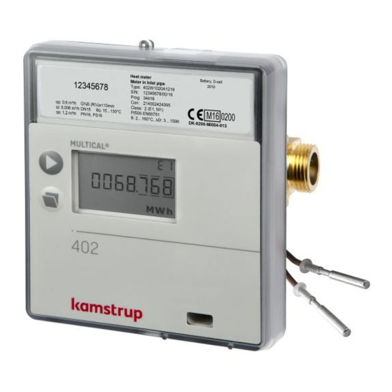
MULTICAL® 402
Reading Office
Aberdeen Office
Cutbush Park, Danehill, Lower Earley,
Unit 6 Airside Business Park, Kirkhill Industrial Estate,
Reading, Berkshire. RG6 4UT. UK.
Dyce, Aberdeen. AB21 0GT. UK.
Tel: +44 (0)118 9311188
Tel: +44 (0)1224 725999
Email: info@able.co.uk
Email: ab@able.co.uk
Internet: www.able.co.uk
e-procurement: www.247able.com
Registered in England No: 01851002
VAT No: GB 417 2481 61
Advertisement
Table of Contents

Related Manuals for Kamstrup MULTICAL 402


Summary of Contents for Kamstrup MULTICAL 402
- Page 1 Installation & Maintenance Instructions MULTICAL® 402 Reading Office Aberdeen Office Cutbush Park, Danehill, Lower Earley, Unit 6 Airside Business Park, Kirkhill Industrial Estate, Internet: www.able.co.uk Reading, Berkshire. RG6 4UT. UK. Dyce, Aberdeen. AB21 0GT. UK. e-procurement: www.247able.com Tel: +44 (0)118 9311188 Tel: +44 (0)1224 725999 Registered in England No: 01851002 Email: info@able.co.uk...
- Page 2 Readings When the top front key is activated, a new reading appears. The lower front key displays historical readings and average values. Four min. after the latest activation of the front key the meter automatically switches to consumed energy. www.kamstrup.com...
- Page 3 MULTICAL® 402 English Kamstrup A/S Industrivej 28, Stilling, DK-8660 Skanderborg Tel: +45 89 93 10 00 · Fax: +45 89 93 10 01 info@kamstrup.com · www.kamstrup.com...
- Page 4 MULTICAL® 402, type 402-W and 402-T must be connected to a tem- perature sensor set type Pt500. MULTICAL® 402, type 402-V must be connected to a temperature sensor set type Pt100. Battery for replacement Kamstrup type 402-000-2000-000 (D-cell) or 402-000-1000-000 (2 x AA-cells).
-
Page 5: Table Of Contents
Contents General information Mounting of temperature sensors Pocket sensor set Short direct sensor set Information codes ”INFO” Mounting of flow sensor Mounting of glands and short direct sensor mounted in MULTICAL®402 flow part Mounting of MULTICAL® 402 Installation examples Mounting the calculator Compact mounting Wall mounting Power supply... -
Page 6: General Information
1. General information Read this guide before installing the meter. In case of incorrect mounting Kamstrup’s guarantee obligations no longer apply. Please note that the following installation conditions must be obeyed: - Pressure stage PN16/PN25, see marking. The flow sensor marking does not apply to... -
Page 7: Pocket Sensor Set
Pocket sensor set Preferably, sensor pockets must be mounted in tee-pieces or in 45° lat- eral Y-pieces. The tip of the sensor pocket must point against the flow direction and be placed in the middle of the water flow. Temperature sensors should be inserted to the bottom of the pockets. If a short response time is required, “non-hardening”... -
Page 8: Short Direct Sensor Set
R1 and built-in M10 union for the short direct sensor. For mounting in existing heating installations with standard angle tees Kamstrup A/S can supply R½ and R¾ brass nipples fitting the short direct sensors. Short direct sensors can also be fitted directly into all Kamstrup’s ULTRAFLOW®... -
Page 9: Mounting Of Flow Sensor
Mounting of glands and short direct sensor mounted in MULTICAL®402 flow part The short direct sensor from Kamstrup can only be mounted in PN16 installations. The blind plug mounted in the MULITCAL® 402 flow part can be used in connection with both PN16 and PN25. - Page 10 Gasket Gasket Tightening approx. 4 Nm The flow meter can be used in both PN16 and PN25 and can be sup- plied marked either PN16 or PN25 as desired. Possibly supplied glands can only be used for PN16. For PN25 installa- tions shall be used suitable PN25 glands.
- Page 11 A Recommended flow sensor position B Recommended flow sensor position C Unacceptable position due to risk of air build-up D Acceptable in closed systems. Unacceptable position in open sys- tems due to risk of air build-up in the system E A flow sensor ought not to be placed immediately after a valve, with the exception of block valves (ball valve type) which must be fully open when not used for blocking F A flow sensor should not be placed at the suction side of a pump...
-
Page 12: Mounting Of Multical® 402
Mounting of MULTICAL® 402 90° 90° MULTICAL® 402 can be mounted vertically, horizontally or at an angle MULTICAL® 402 may be turned up to max. 45° and downwards for max. 90° in relation to the pipe axis. MULTICAL® 402 must not be mounted with the plastic box pointing upwards... -
Page 13: Installation Examples
Installation examples Threaded meter: Flow from the left Flow from the right Flange meter: Flow from the left Flow from the right 4.3.1 Humidity and condensation If MULTICAL® 402 is installed in moist environments, it must be turned 45° relative to the pipe axis as shown in the drawing below. If there is risk of condensation, 45°... -
Page 14: Mounting The Calculator
5. Mounting the calculator The MULTICAL® 402 calculator can be mounted in two different ways: Compact mounting The calculator is mounted direct on the flow sensor. After mounting the calculator is sealed with seal and locking wire. In case of strong conden- sation (e.g. -
Page 15: Power Supply
The battery cannot and must not be charged and must not be short- circuited. Used batteries must be handed in for approved de-struction, f.inst. at Kamstrup A/S. Mains modules The modules are protection class II and are connected via a two-wire cable (without earth) through the cable bush of the calculator placed in the right side of the connecting base. -
Page 16: Testing The Function
24 VAC Supply 230 VAC Supply Black Black 24 VAC 230 VAC F.inst. transformer 230/24 V, type This module is used for direct 66-99-403, can be used. mains connection. Note! MULTICAL® 402 cannot be Note! External supply must be con- supplied by 24 VDC. -
Page 17: Plug-In Modules
9. Plug-in modules A number of extra functions can be added to MULTICAL® 402 by means of plug-in modules. The individual modules are briefly described below. Pulse inputs Pulse inputs (VA) and (VB) are used for the connection of extra water meters with either Reed switch output or passive electronic pulse output. -
Page 18: Data + Pulse Inputs, Type 402-0-10
Data + pulse inputs, type 402-0-10 The data terminals are used for connection of e.g. a PC. The signal is passive and galvani- cally separated by means of optocoup-lers. Conversion into RS232 level requires connec- tion of data cable 66-99-106 (D-Sub 9F) or 66-99-098 (USB) with the fol- lowing connections: Brown... -
Page 19: M-Bus + Pulse Inputs, Type 402-0-20
M-Bus + pulse inputs, type 402-0-20 M-Bus module with primary, secondary and enhanced secondary addressing. The module is connected to an M-Bus master via terminals 24 and 25 using a twisted pair. The polarity is unimportant. The module is powered by the connected master. -
Page 20: Wireless M-Bus, Type 402-0-30, 402-0-35 And 402-0-37
9.10 Radio+ pulse inputs, type 402-0-42 and 402-0-44 The radio modules have been optimized to form part of a Kamstrup radio network system, which operates in the licence-free frequency band in the 434 MHz area, but can also be used for the hand-held reading systems in the same frequency area. -
Page 21: Radio+ Pulse Outputs, Type 402-0-43 And 402-0-45
9.11 Radio+ pulse outputs, type 402-0-43 and 402-0-45 The radio modules have been optimized to form part of a Kamstrup radio network system, which operates in the licence-free frequency band in the 434 MHz area, but can also be used for the hand-held reading systems in the same frequency area. -
Page 22: Module Overview
9.12 Module overview MULTICAL® 402 Communication modules Type No. Description Module No. 402-0-10 Data + 2 pulse inputs (VA, VB) 5550-1025 402-0-11 Data + 2 pulse outputs (CE, CV) 5550-1026 402-0-20 M-Bus + 2 pulse inputs (VA, VB) 5550-1030 402-0-21 M-Bus + 2 pulse outputs (CE, CV) 5505-1007 402-0-29... -
Page 23: Setup Via Front Keys
10. Setup via front keys Date, time and primary M-Bus address can be adjusted by means of the keys on the calculator’s front. 1 In the display you select the reading you want to change 2 Disconnect the supply plug from the meter 3 Wait until the meter has switched off (up to 2.5 minutes). - Page 24 Pressing the main key you go to the next digit from right to left: The active digit flashes and this digit can now be changed by pressing the subkey . You go to the first digit on the right by means of the main key When the value of the reading has been changed you quit by pressing the main key...
- Page 26 5512772_C4_GB_12.2013...
- Page 27 Consumed energy in kWh, Latest target date MWh or GJ Energy count on latest target date followed by energy count on last year’s target date Followed by monthly counts Consumed district heating water Latest target date Volume count on latest target date followed by volume count on last year’s target date...
- Page 28 The calculator’s program number. In this example: Flow meter in outlet pipe, MWh and 100 imp/l. Followed by the calculator’s DDD = 213 configuration number and (*) DDD = 212 software edition. Also see interactive user guides at Display test www.kamstrup.com 5512772_C4_GB_12.2013...
Need help?
Do you have a question about the MULTICAL 402 and is the answer not in the manual?
Questions and answers