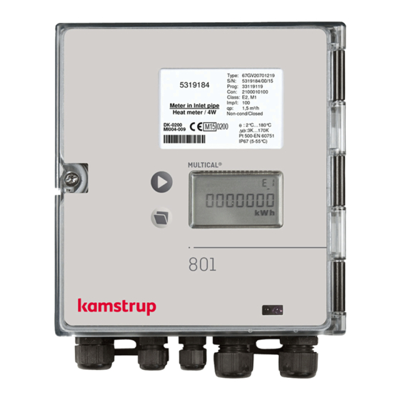
Kamstrup MULTICAL 801 Technical Description
Hide thumbs
Also See for MULTICAL 801:
- Installation manual (12 pages) ,
- Installation and user manual (28 pages)

Related Manuals for Kamstrup MULTICAL 801


Summary of Contents for Kamstrup MULTICAL 801
- Page 1 Technical Description MULTICAL® 801 Kamstrup A/S · Industrivej 28, Stilling · DK-8660 Skanderborg · T: +45 89 93 10 00 · info@kamstrup.com · kamstrup.com...
- Page 2 MULTICAL® 801 Kamstrup A/S · Technical Description · 5512-571_R1_GB_11_2016...
-
Page 3: Table Of Contents
Min. and max. flow and power, V1 ...................... 43 Temperature measurement ......................... 44 Display functions ..........................46 6.10 Info codes ............................51 6.11 Tariff functions ........................... 54 6.12 Data loggers ............................58 6.13 Leak surveillance ..........................60 Kamstrup A/S · Technical Description · 5512-571_R1_GB _11.2016... - Page 4 True energy calculation ........................104 METERTOOL HCW ....................105 14.1 Introduction ............................. 105 14.2 How to use METERTOOL HCW for MULTICAL ® 801 ................106 14.3 Verification using METERTOOL HCW ....................112 14.4 LogView HCW ........................... 115 Kamstrup A/S · Technical Description · 5512-571_R1_GB_11_2016...
- Page 5 Approvals ........................ 117 15.1 Type approvals ..........................117 15.2 The Measuring Instrument Directive ....................117 Troubleshooting ...................... 118 Environmental declaration ..................119 17.1 Disposal ............................119 17.2 Transport restrictions ........................119 Documents ......................120 Kamstrup A/S · Technical Description · 5512-571_R1_GB _11.2016...
-
Page 6: General Description
601. However, many extra facilities such as back MULTICAL ® ® illuminated display, back up of energy metering during power failure, extra communication channels and the option of four analog outputs have been added. 1.1 Block diagram Kamstrup A/S · Technical Description · 5512-571_R1_GB_11_2016... -
Page 7: Technical Data
0.6 m /h…30000 m EN 1434 designation Environmental class A and C MID designation Mechanical environment: Class M1 Electromagnetic environment: Class E1 and E2 Non-condensing environment, closed location 5…55 °C (indoors) Kamstrup A/S · Technical Description · 5512-571_R1_GB _11.2016... -
Page 8: Electrical Data
10 years’ normal operation (with mains supply) Backup period 1 year (without supply) The replacement interval is reduced at high ambient temperature EMC data Fulfils EN 1434 class A and C (MID class E1 and E2) Kamstrup A/S · Technical Description · 5512-571_R1_GB_11_2016... - Page 9 2 x 0.25 mm : 10 m 4 x 0.25 mm : 100 m 2 x 0.50 mm : 5 m 2 x 0.50 mm : 20 m 2 x 1,00 mm : 10 m Kamstrup A/S · Technical Description · 5512-571_R1_GB _11.2016...
-
Page 10: Mechanical Data
Cable adapters 6 pcs. D 3…6 mm and 3 pcs. D 4…8 mm 2.4 Material Top cover Connection base PC + 10 %GF Sealing cover, top Sealing cover, bottom Prism behind display PMMA Kamstrup A/S · Technical Description · 5512-571_R1_GB_11_2016... -
Page 11: Accuracy
MULTICAL® 801 2.5 Accuracy Figure 1 MULTICAL ® 801 typical accuracy compared to EN 1434. Kamstrup A/S · Technical Description · 5512-571_R1_GB _11.2016... -
Page 12: Type Overview
We currently develop new functions and modules for MULTICAL ® 801. Please contact Kamstrup A/S if your application is not covered by the variants shown. 3.1 Type and programming overview... -
Page 13: Type Number Composition
MULTICAL 801 carton. The cable between MULTICAL 801 and ULTRAFLOW it not connected from the factory. **) GSM module and RF module are NOT combinable in one meter. Kamstrup A/S · Technical Description · 5512-571_R1_GB _11.2016... -
Page 14: Prog, A-B-Ccc-Ccc
Infrared optical reading head RS232 w/D-sub 9F 66-99-106 Data cable RS232, D-sub 9F 66-99-136 Infrared optical reading head for Kamstrup/EVL w/RS232 w/D-sub 9F 66-99-144 Infrared optical reading head for Kamstrup/EVL w/USB plug 66-99-370 Verification unit, Pt100 (to be used with METERTOOL) - Page 15 CCC (V1) Flow meter position - Inlet (at T1) k-factor table - Outlet (at T2) Measuring unit, Energy - x10 GJ - GJ - kWh - MWh - Gcal Flow meter coding (CCC-table) Kamstrup A/S · Technical Description · 5512-571_R1_GB _11.2016...
- Page 16 [kWh] qp 0.6 m /h…15 m [MWh] qp 0.6 m /h…15000 m [GJ] qp 0.6 m /h…30000 m Kamstrup A/S · Technical Description · 5512-571_R1_GB_11_2016...
- Page 17 2359260 1-2-7-8 3932100 65-X-CLBG-XXX 1-2-7-8 5000 471852 65-X-CMBH-XXX 1-2-7-8 65-X-CMBJ-XXX 471852 1-2-7-8 2500 943704 65-X-FACL-XXX 1-2-7-8 943704 1-2-7-8 1500 1572840 65-X-FBCL-XXX 1-2-7-8 1572840 1-2-7-8 2359260 65-5-FCCN-XXX 1-2-7-8-N 589815 65-5-FECN-XXX 1-2-7-8-N 65-5-FECP-XXX 65-5-FECR-XXX Kamstrup A/S · Technical Description · 5512-571_R1_GB _11.2016...
- Page 18 65 54 BCX 1-2-7-8 9437040 0.25 1000 65 54 BKX 1-2-7-8 393210 60.0 65 54 XXX 1-2-7-8 Current flow indication (l/h or m³/h) is calculated based on volume pulses/10 s (see paragraph 6.5) Kamstrup A/S · Technical Description · 5512-571_R1_GB_11_2016...
- Page 19 65-X-FECP-XXX 65-X-FECR-XXX 943704 0.25 65-X-FFCP-XXX 1-2-7-8-N 65-X-FFCR-XXX 1000 65-X-F1BR-XXX 1000 65-X-F1CR-XXX 1572840 0.15 1000 65-X-FGBR-XXX 1-2-7-8-N Current flow indication (l/h or m³/h) is calculated based on volume pulses/10 s (see paragraph 6.5) Kamstrup A/S · Technical Description · 5512-571_R1_GB _11.2016...
- Page 20 1-2-7-8-N 943704 1-2-7-8-N 1572840 1-2-7-8 2359260 1-2-7-8-N 589815 1-2-7-8-N 943704 0.25 1-2-7-8-N 1000 1572840 0.15 1000 1-2-7-8 Current flow indication (l/h or m³/h) is calculated based on volume pulses/10 s (see paragraph 6.5) Kamstrup A/S · Technical Description · 5512-571_R1_GB_11_2016...
- Page 21 Current flow indication (l/h or m³/h) is calculated based on volume pulses/10 s (see paragraph 6.5) *) Under this CCC code, the count will display the seven most significant digtes, followed by “0” Kamstrup A/S · Technical Description · 5512-571_R1_GB _11.2016...
- Page 22 393735 59.92 GWF/U2 5259161 4.486 15/25 HM/WS 1386 1702208 1.386 HM/WS 471852 Westland Current flow indication (l/h or m³/h) is calculated based on volume pulses/10 s (see paragraph 6.5) * Multiple-jet water meter Kamstrup A/S · Technical Description · 5512-571_R1_GB_11_2016...
- Page 23 Note: Continuous maximum water flow and permanent ∆Θ > 75 K may cause overflow in the daily data logger at CCC=010-011-012-013-150-202-205-206. With these combinations, we recommend you to use the built Prog. data logger. Kamstrup A/S · Technical Description · 5512-571_R1_GB _11.2016...
-
Page 24: Display Coding
Max. yearly data • 14.3 This year’s min. • 14.4 Min. yearly data • 14.5 This month’s max. 14.6 Max. monthly data • 14.7 This month’s min. • • 14.8 Min. monthly data Kamstrup A/S · Technical Description · 5512-571_R1_GB_11_2016... - Page 25 Number of yearly data displayed (1…15) Number of monthly data displayed (1…36) DDD=210 is the ”standard code” of heat meters with meter type 67xxxxxxx2xx. Please contact Kamstrup for other combinations. A DDD-code can contain max. 103 readings, including 4 data logger readings. Top module no.
-
Page 26: Ee< Configuration Of Multi-Tariff
(T1<T2). (Recommended for heat/cooling applications) • • Energy if P>TL2 is saved in TA2 and energy if Q>TL3 is saved in TA3 PQ-tariff See paragraph 6.9 for further details on the tariff registers. Kamstrup A/S · Technical Description · 5512-571_R1_GB_11_2016... -
Page 27: Ff< Input A (Va), Pulse Division >Gg< Input B (Vb), Pulse Division
EL A/EL b (kWh) 0000000 75 kW 75 kW 10.00 EL A/EL b (kWh) 0000000 15 kW 15 kW 2.000 EL A/EL b (kWh) 0000000 25000 kW 25000 kW 10000 EL A/EL b (MWh) 00000.00 Kamstrup A/S · Technical Description · 5512-571_R1_GB _11.2016... -
Page 28: Mn< Configuration Of Leak Limits
Note: M=2 and N=2 are default values when leak surveillance is used. Increased sensitivity, e.g. M=4, can only be achieved using METERTOOL. Info codes for leakage/burst are only active when M 0 or N 0 respectively. > > Kamstrup A/S · Technical Description · 5512-571_R1_GB_11_2016... -
Page 29: Data For Configuration
Reserved: These registers are prepared for later extensions of the functionality of the modules. Therefore, they have no actual designations yet. -COUNTRY CODES Information on country codes see 55 14-170 - MAINTENANCE See instructions no. 55 08-709 concerning update of programming and configuration. Kamstrup A/S · Technical Description · 5512-571_R1_GB _11.2016... -
Page 30: Dimensioned Sketches
MULTICAL® 801 4 Dimensioned sketches Front measurements of MULTICAL Installation measurements of MULTICAL ® ® Wallmounted MULTICAL 801 seen from the side Cable unions of MULTICAL ® ® All measurements in [mm] Kamstrup A/S · Technical Description · 5512-571_R1_GB_11_2016... -
Page 31: Installation
Outlet table k-factor for A=3 (Flow T1 in sensor in V1 and inlet pipe) Outlet table Cooling meter E3=V1(T2-T1)k k-factor for A=4 (Flow T2 in sensor in V1 and outlet pipe) Inlet table Kamstrup A/S · Technical Description · 5512-571_R1_GB _11.2016... -
Page 32: Emc Conditions
801 has many connection options. The terminals are placed at the bottom of the meter. Additional information can be found in Section 7 (Flow Meter Connection), Section 8 (Temperature Sensors) and Section 9 (Other connections). Kamstrup A/S · Technical Description · 5512-571_R1_GB_11_2016... -
Page 33: Calculator Functions
Cooling energy: E3 = V1 (T2-T1)k is the heat coefficient of water which is calculated on the basis of the formula stated in EN 1434-1:2007 (identical with the energy formula of OIML R75-1:2002). For checking the measurement, Kamstrup can supply an energy calculator:... -
Page 34: Application Types
T3 can be used for checking the measurement of either inlet for outlet temperature, but T3 is not used for calculation. Mass: M1 = V1 (Kmass t1) Mass: M2 = V2 (Kmass t2) Kamstrup A/S · Technical Description · 5512-571_R1_GB_11_2016... - Page 35 Open system with tapping from outlet pipe Heat energy: E1 = V1(T1-T2)k T1:Inlet Tap water energy: E5 = V2 (T2-T3)k T2:Inlet T3 is measured or programmed Mass: M1 = V1 (Kmass t1) Mass: M2 = V2 (Kmass t2) Kamstrup A/S · Technical Description · 5512-571_R1_GB _11.2016...
- Page 36 T3 is measured or programmed Mass: M1 = V1 (Kmass t1) Mass: M2 = V2 (Kmass t2) Application no. 8 Hot water boiler with circulation Total consumption E1 = V1(T1-T2)k T2:Outlet Circulated consumption: E7 = V2(T1-T3)k T3:Outlet Kamstrup A/S · Technical Description · 5512-571_R1_GB_11_2016...
- Page 37 Two-stage boiler system with 1 flow meter Boiler energy „B“: E3 = V1 (T2-T1)k T1:Outlet Boiler energy „A“: E4 = V1(T1-T3)k T1:Inlet * M2 = V2 (Kmass t3)* only with delivery codes (930…939)! Kamstrup A/S · Technical Description · 5512-571_R1_GB _11.2016...
- Page 38 Average of inlet Average of Volume reading pipe outlet pipe 2003.06.01 534.26 m 48236 18654 2002.06.01 236.87 m 20123 7651 28113/297.39 11003/297.39 Yearly 297.39 m 28113 11003 consumption = 94.53°C = 36.99°C Table 1 Kamstrup A/S · Technical Description · 5512-571_R1_GB_11_2016...
-
Page 39: Calculator With Two Flow Sensors
Electric welding can occur Electric welding must always be carried out with the earth pole closest to the welding point. Our factory guarantee does not comprise damage to meters due to welding. Kamstrup A/S · Technical Description · 5512-571_R1_GB _11.2016... -
Page 40: Combined Heat/Cooling Metering
25°C. If the meter is to be used for ”purchase and sale of heat”, T1 limit is adjusted to 180.00°C, which cancels the T1 limit function. The change between heat and cooling measurement involves no hysteresis (∆T1 limit = 0.00K). Kamstrup A/S · Technical Description · 5512-571_R1_GB_11_2016... -
Page 41: Flow Measurement V1 And V2
V1 and V2 must be the same type (either quick (CCC > 100) or slow (CCC=0XX)) but can have different qp-codings (CCC). The actual flow rate on the display will be shown a ”0”, when the period between pulses exceed 15 min. Kamstrup A/S · Technical Description · 5512-571_R1_GB _11.2016... -
Page 42: Power Measurement, V1
T1 = 70.00°C and T2 = 30.00°C, k-factor is calculated at 1.156 kWh/m P = 0.316 (70-30) x 1.156 = 14.6 Current power in V1 Both heat and cooling power is displayed numerically (without signs) Kamstrup A/S · Technical Description · 5512-571_R1_GB_11_2016... -
Page 43: Min. And Max. Flow And Power, V1
Furthermore, the back-up battery of MULTICAL 801 ought to be replaced at intervals of max. 10 years. Value of year-to-date max. Date of year-to-date max. Value of this month’s min. Date of this month’s min. Kamstrup A/S · Technical Description · 5512-571_R1_GB _11.2016... -
Page 44: Temperature Measurement
1/1000 K. Pt100 Pt500 Measuring current < 3 mA < 0.5 mA Peak power < 1.5 mW < 0.2 mW RMS influence < 10 µW < 1 µW Kamstrup A/S · Technical Description · 5512-571_R1_GB_11_2016... - Page 45 E4, E5, E6 and E7 (see application drawings in paragraph 6.2) The temperatures can be entered from the factory or by means of METERTOOL, in the range 0.01…180°C, after installation. Kamstrup A/S · Technical Description · 5512-571_R1_GB _11.2016...
-
Page 46: Display Functions
The bottom pushbutton is used to collect secondary information on the primary indication selected. Example: If the selected primary indication is ”heat energy”, the secondary indications will be yearly data and monthly data for heat energy. Kamstrup A/S · Technical Description · 5512-571_R1_GB_11_2016... - Page 47 MULTICAL® 801 Heat energy E1 in MWh Yearly data, date of LOG1 (latest yearly reading) Yearly data, value of LOG1 (latest yearly reading) Monthly data, date of LOG1 (latest monthly reading) Kamstrup A/S · Technical Description · 5512-571_R1_GB _11.2016...
- Page 48 2 yearly data and 12 monthly data. The target date will be the standard date applying to the delivery code used. As the display is configured to the customer’s need (selecting the DDD-code) the display will most frequently include much fewer indications than listed below. Figure 2 Kamstrup A/S · Technical Description · 5512-571_R1_GB_11_2016...
- Page 49 • • • • • 14.5 This month’s max. • • • • • 14.6 Max. monthly data • • • • • 14.7 This month’s min. • • • • • Kamstrup A/S · Technical Description · 5512-571_R1_GB _11.2016...
- Page 50 External modulesecondary adr. • • • • • • Display example showing the PROG number. A total survey of existing display codes (DDD) appear from a separate document. Please contact Kamstrup for further details. Kamstrup A/S · Technical Description · 5512-571_R1_GB_11_2016...
-
Page 51: Info Codes
LogView. Furthermore, the info code is saved in the programmable logger, in the daily logger, in the monthly logger and in the yearly logger for diagnosis purposes. Kamstrup A/S · Technical Description · 5512-571_R1_GB _11.2016... - Page 52 This prevents ”infoevent” from counting during transportation and non-relevant data from appearing in the info logger. When the meter has accumulated the volume register the first time after the installation, the info code automatically becomes active. Kamstrup A/S · Technical Description · 5512-571_R1_GB_11_2016...
- Page 53 When Info is set and when Info is deleted. Max. once every 120 s. When Info is set and when Info is 16, 128, 1024, 2048, deleted. 4096, 8192, 16384, 32768 Max. once a day Kamstrup A/S · Technical Description · 5512-571_R1_GB _11.2016...
-
Page 54: Tariff Functions
2 tariff conditions, TL2 and TL3, which are always used in the same tariff type, are connected to each tariff function. However, it is not possible to “mix” two tariff types. Example: EE=11 (Power tariff) TA2 shows energy consumed… …above power limit TL2 (but below TL3) Kamstrup A/S · Technical Description · 5512-571_R1_GB_11_2016... - Page 55 If either power or flow tariff is used you obtain an overview of the total consumption compared to the part of the consumption used above tariff limit. Kamstrup A/S · Technical Description · 5512-571_R1_GB _11.2016...
- Page 56 Setting up data TL3 must always be bigger than TL2. The outlet temperature tariff can be used as a basis for weighted user charge. A high outlet temperature indicates insufficient heat utilization, which is uneconomical for the heat supplier. Kamstrup A/S · Technical Description · 5512-571_R1_GB_11_2016...
- Page 57 Accumulation in TA2, TA3 and main P > TL2 and q > TL3 register The PQ tariff can e.g. be used for customers paying a fixed charge based on max. power and max. flow. Kamstrup A/S · Technical Description · 5512-571_R1_GB _11.2016...
-
Page 58: Data Loggers
MIN. POWER V1 Value for min. power during period ♦ T1avg Time average of T1 ♦ T2avg Time average of T2 ♦ T3avg Time average of T3 ♦ P1avg Time average of P1 Kamstrup A/S · Technical Description · 5512-571_R1_GB_11_2016... - Page 59 Date (YY.MM.DD) Year, month and day of logging time info Information code on above date When the info logger is read in the display the latest 36 changes including dates can be read. Kamstrup A/S · Technical Description · 5512-571_R1_GB _11.2016...
-
Page 60: Leak Surveillance
Note: M=2 is the default value when leak surveillance is used. Increased sensitivity, e.g. M=4, can only be achieved by means of METERTOOL. Info codes for leakage/burst are only active when M > 0 or N > 0 respectively. Kamstrup A/S · Technical Description · 5512-571_R1_GB_11_2016... - Page 61 SMS message to the customer’s mobile phone parallel with the heating station on guard receiving the message. Regular data readings from MULTICAL 801 to receiving station/control centre ensure that defective remote readings, if any, are detected. Kamstrup A/S · Technical Description · 5512-571_R1_GB _11.2016...
- Page 62 This limitation has been introduced in order to avoid erroneous alarms due to the installation and the shortened measuring period. The alarm function can be tested via remote communication by pressing both pushbuttons at a time until “Call” is displayed. Kamstrup A/S · Technical Description · 5512-571_R1_GB_11_2016...
-
Page 63: Reset Functions
Note: ”Date” is after reset set to 2000.01.01 and subsequently changed to current date/time from the PC used for the task. Therefore, do not forget to check correct date/time (technical normal time = ”winter time”) of the PC before starting the reset function via METERTOOL. Kamstrup A/S · Technical Description · 5512-571_R1_GB _11.2016... -
Page 64: Sms Commands
See the examples on the next page. NOTE: SMS commands must be written in either capital letters or small letters, i.e. an SMS command must not include a mixture of capital and small letters. Kamstrup A/S · Technical Description · 5512-571_R1_GB_11_2016... - Page 65 Example of correct reply 6930 Hours, Meter No.: 6055524 SIGNAL – for reading the signal strength Syntax, command =SIGNAL# Return reply, error NO ANSWER Example of SMS command =SIGNAL# Example of correct reply Signal: 16(0-31) Kamstrup A/S · Technical Description · 5512-571_R1_GB _11.2016...
-
Page 66: Flow Meter Connection
CCC-code must be in the area 010 ≤ CCC ≤ 022. Example: CCC=012 is suitable for a mechanical flow meter with 100 litres/imp. Flow sensors with Qmax. in the range of 10…300 m /h can use this CCC-code. Kamstrup A/S · Technical Description · 5512-571_R1_GB_11_2016... -
Page 67: Flow Meter With Active 24 V Pulse Output
Flow sensor with active output, supplied through MULTICAL This connection is used together with both Kamstrup’s ULTRAFLOW and Kamstrup’s electronic pick-up units for vane wheel meters. The current consumption of these units is very low and furthermore adapted to the battery lifetime ... - Page 68 100 m between flow sensor and calculator. Figure 6 The active pulse output is direct connected to the galvanically separated flow sensor input. This permits a cable length of up to 100 m between flow sensor and calculator. Kamstrup A/S · Technical Description · 5512-571_R1_GB_11_2016...
- Page 69 Auxiliary voltage from E+ and E- is added to the passive contact output P before the signal is connected to the galvanically separated flow sensor input. This permits a cable length of up to 100 m between flow sensor and calculator. Kamstrup A/S · Technical Description · 5512-571_R1_GB _11.2016...
- Page 70 Auxiliary voltage from terminals 97A and 98A is added to the passive contact output on terminals 56 and 57 before the signal is connected to the galvanically separated flow sensor input. This permits a cable length of up to 100 m between flow sensor and calculator. Kamstrup A/S · Technical Description · 5512-571_R1_GB_11_2016...
- Page 71 ”back to back”, whereby one of the meters will measure flow, which one depends on the flow direction. ULTRAFLOW is connected to the non-galvanically separated inputs. Up to 10 m cable length between flow ® meter and calculator is thus possible. Kamstrup A/S · Technical Description · 5512-571_R1_GB _11.2016...
- Page 72 [ton] 235926 10…100 FUS380 DN50-65 589815 40…200 FUS380 DN80-100 589815 100…400 FUS380 DN125 235926 150…1200 1600 FUS380 DN150-250 1179630 0.02 500…3000 3600 FUS380 DN300-400 2359260 0.01 1400…18000 36000 FUS380 DN500-1200 Table 3 Kamstrup A/S · Technical Description · 5512-571_R1_GB_11_2016...
-
Page 73: Pulse Inputs Va And Vb
Monthly data, up to latest 36 months • Counter values VA and VB can be preset to the value of the connected meters at the time of commissioning by means of METERTOOL. Kamstrup A/S · Technical Description · 5512-571_R1_GB _11.2016... - Page 74 Meter no. of VA (max. 8 digits Yearly data, date of LOG1 (latest target date) Yearly data, value of LOG1 (latest yearly reading) This is the accumulated volume registered on 1 June 2012 Kamstrup A/S · Technical Description · 5512-571_R1_GB_11_2016...
-
Page 75: Temperature Sensors
159.191 159.564 159.937 160.309 160.682 161.054 161.427 161.799 162.171 162.543 162.915 163.286 163.658 164.030 164.401 164.772 165.143 165.514 165.885 166.256 166.627 166.997 167.368 167.738 168.108 Pt100, IEC 751 Amendment 2-1995-07 Table 4 Kamstrup A/S · Technical Description · 5512-571_R1_GB _11.2016... -
Page 76: Sensor Types
Short direct sensor pair with 1.5 m cable Short direct sensor pair with 3.0 m cable Set of 3 pocket sensors with 1.5 m cable Set of 3 short direct sensors with 1.5 m cable Kamstrup A/S · Technical Description · 5512-571_R1_GB_11_2016... -
Page 77: Cable Influence And Compensation
The limitations connected to the use of 2-wire sensor sets according to EN 1434-2 appear from the table below. Kamstrup supply Pt500 sensor sets with up to 10 m cable (2 x 0.25 mm Pt100 sensors... - Page 78 PVC cables are normally used up to 80°C and for higher temperatures, silicone cables are often used. Kamstrup’s 4-wire sensor pair has a replaceable sensor insert and is available in lengths of 90, 140 and 180 mm. Kamstrup A/S · Technical Description · 5512-571_R1_GB_11_2016...
-
Page 79: Pocket Sensors
Figure 16 Figure 17 The stainless steel pockets can be for mounting in PN25 systems! Kamstrup A/S · Technical Description · 5512-571_R1_GB _11.2016... -
Page 80: Pt500 Short Direct Sensor Pair
6556-475 6556-476 6556-526 6556-527 G½ G¾ G1¼ G1½ Recommended DS 27.5 mm DS 27.5 mm DS 27.5 mm DS 38 mm DS 38 mm temperature sensor Max. 130 °C and PN16 Figure 20 Kamstrup A/S · Technical Description · 5512-571_R1_GB_11_2016... -
Page 81: Other Connections
2) By means of METERTOOL a ”normal reset” is carried out under ”UTILITY Reset”. After this, the new values have been stored in the meter’s memory. Kamstrup A/S · Technical Description · 5512-571_R1_GB _11.2016... -
Page 82: Data Connection [62-64]
Adaption to RS 232 level is possible via data cable type 66-99-106. Adaption to USB is possible via data cable 66-99-098. The data connection uses the KMP protocol. Please contact Kamstrup for further details on the KMP protocol. 9.4 Valve control [16B-18B]... -
Page 83: Auxiliary Supply [97A-98A]
The auxiliary supply is suitable for e.g. supplying a Lon-module or a passive flow meter output. The built in auxiliary supply is available on terminals 97A-98A. The voltage on terminals 97A-98A varies according to load. Kamstrup A/S · Technical Description · 5512-571_R1_GB _11.2016... -
Page 84: Power Supply
METERTOOL. After a storage period of three years, we recommend that you scrap the back-up battery. Kamstrup A/S · Technical Description · 5512-571_R1_GB_11_2016... -
Page 85: Vac Supply
National regulations for electric installations must be observed. The 24 VAC module can be connected/disconnected by the heating station’s personnel, whereas the fixed 230/24 V installation into the meter panel must be carried out by an authorized electrician. Kamstrup A/S · Technical Description · 5512-571_R1_GB _11.2016... -
Page 86: For Multical ® 801 With Both Analog Outputs And High-Power Communication We Recommend A Stronger
For MULTICAL ® 801 with both analog outputs and high-power communication we recommend a stronger transformer, e.g. type 5920-161. Maximum cable length between 230/24 VAC transformer e.g. Kamstrup type 6699-403 and MULTICAL ® Cable type Maximum length 2 x 0.75 m 50 m 2 x 1.5 mm... -
Page 87: Danish Regulations For The Connection Of Mains Operated Meters
This task can also be carried out by persons or companies, who professionally produce, repair or maintain equipment if only the person carrying out the work has the necessary expert knowledge. Kamstrup A/S · Technical Description · 5512-571_R1_GB _11.2016... -
Page 88: Plug-In Modules
ZigBee 2.4 GHz int.ant. + pulse inputs Metasys N2 (RS485) + pulse inputs Siox module (Auto detect Baud rate) BACnet MS/TP + pulse inputs Modbus RTU + pulse inputs High Power Radio Router + pulse inputs Kamstrup A/S · Technical Description · 5512-571_R1_GB_11_2016... - Page 89 MULTICAL® 801 Kamstrup A/S · Technical Description · 5512-571_R1_GB _11.2016...
- Page 90 67-0Q M-Bus MCIII data 67-0V No limitations M-Bus 67-0P M-Bus (Alternative registre) Note: Pulse input VA and VB (terminals 65-66-67-68) is not connected if the module is used in an external communication unit. Kamstrup A/S · Technical Description · 5512-571_R1_GB_11_2016...
- Page 91 The module is available with internal antenna as well as connection for external antenna. The radio module is prepared to form part of a Kamstrup radio network, the read data being automatically transferred to system software via the network component/network unit RF Concentrator.
- Page 92 The M-Bus module 670029 comprises the same data packet as M-Bus module 6604 for MC III/66-C and module 660S for MCC/MC 401. The module can e.g. be used together with the old M-Bus master with display, old regulators and old reading systems not supporting the newer M-Bus modules. Kamstrup A/S · Technical Description · 5512-571_R1_GB_11_2016...
- Page 93 The T1 OMS module supports individual encryption and comes with internal antenna as well as MCX connection for external antenna. Kamstrup recommend that an external antenna is mounted on this module if the meter is fitted with a top module too. This ensures the best possible radio range.
- Page 94 The N2 module for MULTICAL ensures simple integration from Kamstrup’s heat and cooling meters to N2 Open based systems. Adress area is 1-255 determined by the last three digits of the meters customer number.
- Page 95 The BACnet module for MULTICAL ensures simple integration from Kamstrup’s heat, cooling and water meters to BACnet based systems. The Module can be used as either master or slave, depending on the used MAC address.
- Page 96 11.1.20 High Power Radio Router + 2 pulse inputs (VA, VB) (67-00-84) (PCB - 5550-1221) The High Power RadioRouter module has built-in router functionality and is thus optimized to form part of a Kamstrup radio network, the read data being automatically transferred to system software via the network unit RF Concentrator.
-
Page 97: Retrofitting Modules
Configuration of communication address etc. via Module Modbus RTU + pulse inputs Programmer or METERTOOL. High Power Radio Router + pulse inputs Pulse values of VA and VB are changed via METERTOOL Kamstrup A/S · Technical Description · 5512-571_R1_GB _11.2016... - Page 98 Data modules are retrofitted by placing the module in the PCB holder in the left side of the meter and "clicking" on the module. Insert module Module and meter are electrically connected using a 6-pole jumper: Add jumper Kamstrup A/S · Technical Description · 5512-571_R1_GB_11_2016...
-
Page 99: Data Communication
The KMP protocol is used in all Kamstrup consumption meters launched in 2006 and later. The protocol is used on the optical eye and via plug pins for the modules. Thus, modules with e.g. M-bus interface use the KMP protocol internally and the M-bus protocol externally. - Page 100 METER TYPE Software edition CHECK SUM 1 Software check sum HIGH RES High-resolution energy register for test purposes TOP MODULE ID ID number of top module BOTMODULE ID ID number of base module Kamstrup A/S · Technical Description · 5512-571_R1_GB_11_2016...
-
Page 101: Multical 66-Cde Compatible Data
Utilities and other relevant companies who want to develop their own communication driver for the KMP protocol can order a demonstration program in C# (.net based) as well as a detailed protocol description (in English language). 12.2 MULTICAL 66-CDE compatible data Not included in MC801 Kamstrup A/S · Technical Description · 5512-571_R1_GB _11.2016... -
Page 102: Calibration And Verification
13.1.1 Data reading of high-resolution energy The register ”HighRes” can be data read with ID = 155. In connection with data reading, measuring unit and value will be correct irrespective of meter size. Kamstrup A/S · Technical Description · 5512-571_R1_GB_11_2016... -
Page 103: Pulse Interface
10 kOhm can be connected to the external pulse supply via terminal 13A. Pulse interface 66-99-461 placed as module 1 in MULTICAL 13.2.1 Safety diode short- circuits in case of wrong polarity Kamstrup A/S · Technical Description · 5512-571_R1_GB _11.2016... -
Page 104: True Energy Calculation
EN 1434-1:2004 or OIML R75:2002. An energy calculator like the one shown below can be ordered from Kamstrup A/S: The true energy at the most frequently used verification points is indicated in the table below. -
Page 105: Metertool Hcw
When the installation has been completed, the icon ”METERTOOL HCW” will appear in the ‘All Programs’ menu under ‘Kamstrup METERTOOL’ (or from the menu ”start” for Windows XP) and as a link on the desktop. Double-click on link or icon in order to start the program. -
Page 106: How To Use Metertool Hcw For Multical ® 801
MULTICAL 801 uses the Kamstrup Software product “METERTOOL HCW” (66-99-724). Before running the program, connect your optical read-out head to your computer and place the read-out head resting on the two plastic studs intended for this purpose in the lower right-hand corner of the calculator front. - Page 107 It is not possible to change the serial number as it is a unique number allocated to the meter during production. ”V2(CCC)”, ”T1”, ”T2” and ”Max T1 for cooling” can be disabled, depending on the meter type in question. Partial/Total programming Kamstrup A/S · Technical Description · 5512-571_R1_GB _11.2016...
- Page 108 Reset can be carried out via ”Normal reset” in the ”Reset function” (see 14.2.16), by totally de-energizing the meter. 14.2.6 Modules (Advanced Mode) This menu is used to set up modules, which might be installed in the calculator. Setup fields and procedure depend on the module. Kamstrup A/S · Technical Description · 5512-571_R1_GB_11_2016...
- Page 109 Data logger reset: The calculator’s data protocol is reset, which affects the year, month, day and hour log as well as the info code and configuration log. Total Reset: Resets all historical as well as legal registers. Kamstrup A/S · Technical Description · 5512-571_R1_GB _11.2016...
- Page 110 The contact button provides links to Kamstrup’s website and mailbox. Output This function shows the latest functions used in the program. User manual Provides a link to the user manual for the meter on Kamstrup’s website. Kamstrup A/S · Technical Description · 5512-571_R1_GB_11_2016...
- Page 111 The function makes it possible to change between open dialog boxes in the program. 14.2.22 Application Double-click on link or icon in order to start the program. Click “Connect” to establish contact with the meter. Activate “Configuration” in order to start meter configuration. Kamstrup A/S · Technical Description · 5512-571_R1_GB _11.2016...
-
Page 112: Verification Using Metertool Hcw
T3 [°C] 66-99-370 Standard (EN1434/MID) Type 67-F/K (4-wire Pt100) T1 [°C] T2 [°C] T3 [°C] 66-99-371 Standard (EN1434/MID) Type 67-G/L (4-wire Pt500) For other equipment variants (types or temperature points), please contact Kamstrup A/S. Kamstrup A/S · Technical Description · 5512-571_R1_GB_11_2016... - Page 113 “Write” these new data to the equipment. In order to avoid unintentional change of calibration data ”Write” is protected by a password, which can be obtained from Kamstrup A/S. Calibration data include test points, permissible error, uncertainty, ambient temperature (fixed value) and number of integrations per test.
- Page 114 14.3.6 Certificate If you want to print a certificate with saved results, select “Certificate”. The test/verification result can, subsequently, be found according to serial number, and the certificate can be printed. Kamstrup A/S · Technical Description · 5512-571_R1_GB_11_2016...
-
Page 115: Logview Hcw
Reading is carried out by direct connection to the module. Module logger data cannot be read via the MULTICAL 801 calculator. 14.4.5 Help button Contact The contact button gives you the links to Kamstrup’s website and mailbox. Output This function shows the latest functions used in the program. User manual Link to the user manual for the meter on Kamstrup’s website. - Page 116 To zoom out; doubleclick anywhere on the coordinate system. To read exact values on the graphs; deselect Zoom and let the mouse pointer ”hover” over the point of interest. Kamstrup A/S · Technical Description · 5512-571_R1_GB_11_2016...
-
Page 117: Approvals
801 has a national Danish cooling approval, TS 27.02 006, according to BEK 1178 based on EN1434:2007. 15.2 The Measuring Instrument Directive MULTICAL 801 is supplied with marking according to MID (2004/22/EF). The certificates have the following ® numbers: B-module: DK-0200-MI004-009 D-module: DK-0200-MID-D-001 Kamstrup A/S · Technical Description · 5512-571_R1_GB _11.2016... -
Page 118: Troubleshooting
Place the sensors at the bottom of too low, or accumulation of the sensor pockets Heat dissipation energy (e.g. MWh) slightly too Insulate the sensor pockets Too short sensor pockets Replace by longer pockets Kamstrup A/S · Technical Description · 5512-571_R1_GB_11_2016... -
Page 119: Environmental Declaration
MULTICAL® 801 17 Environmental declaration Kamstrup A/S holds an environmental certification according to ISO 14001, and as part of our environment policy we use materials, which can be recovered environmentally correct to the greatest possible extent. Kamstrup A/S has calculated carbon footprint of all meters. -
Page 120: Documents
MULTICAL® 801 18 Documents Danish English German Technical Description 5512-570 5512-571 5512-572 Data sheet 5810-624 5810-625 5810-626 Installation and User’s guide 5512-602 5512-603 5512-604 Kamstrup A/S · Technical Description · 5512-571_R1_GB_11_2016... - Page 121 MULTICAL® 801 Kamstrup A/S · Technical Description · 5512-571_R1_GB _11.2016...
Need help?
Do you have a question about the MULTICAL 801 and is the answer not in the manual?
Questions and answers