Advertisement
Quick Links
Mini-ITX SBC supports AMD® Ryzen™ Embedded V1000/R1000
Series Onboard SoC, DDR4, Triple/Quadruple DP, Dual GbE, M.2,
SATA 6Gb/s, USB 3.2 Gen 1, COM, TPM 2.0, HD Audio and RoHS
Quick Installation Guide
gKINO-V/R1000 package includes the following items:
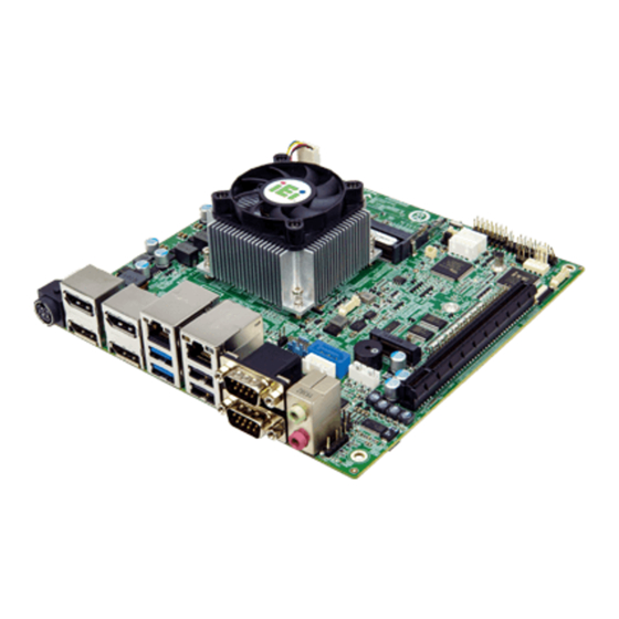
1 x gKINO-V/R1000 single board computer with CPU cooler
1 x I/O shielding
1 x SATA cable
1 x QIG
gKINO-V/R1000
Version 1.0
August 27, 2020
Package List
©2020 Copyright by IEI Integration Corp.
All rights reserved.
Advertisement

Related Manuals for IEI Technology gKINO-V1000 Series


Summary of Contents for IEI Technology gKINO-V1000 Series
- Page 1 Mini-ITX SBC supports AMD® Ryzen™ Embedded V1000/R1000 Series Onboard SoC, DDR4, Triple/Quadruple DP, Dual GbE, M.2, SATA 6Gb/s, USB 3.2 Gen 1, COM, TPM 2.0, HD Audio and RoHS gKINO-V/R1000 Quick Installation Guide Version 1.0 August 27, 2020 Package List gKINO-V/R1000 package includes the following items: 1 x gKINO-V/R1000 single board computer with CPU cooler ...
-
Page 2: Specifications
Specifications SoC: AMD® Ryzen™ Embedded V1605B (quad core, 2 MB cache, 8 CU, 2.0 GHz / up to 3.6 GHz, 12 W – 25 W) AMD® Ryzen™ Embedded V1202B (dual core, 1 MB cache, 3 CU, 2.3 GHz / up to 3.2 GHz, 12 W – 25W) AMD®... - Page 3 Audio: Realtek ALC662 HD audio codec 1 x Digital output connector (S/PDIF) 2 x 6W audio amplifier connector (L+R) 2 x Audio jack (line-out and mic-in) 1 x Front audio connector by 10-pin (2x5) header Front Panel: 1 x Front panel (2x7 pin, power LED, HDD LED, speaker, power button, reset button) ...
-
Page 4: Ordering Information
Operating Temperature: 0°C ~ 60°C Storage Temperature: -10°C ~ 70°C Operation Humidity: 5% ~ 95%, non-condensing Dimensions: 170mm x 170 mm Weight: GW: 900g / NW: 400g Safety: CE, FCC Ordering Information gKINO-V1605B-R10: Mini-ITX SBC supports AMD®... - Page 5 19800-000300-100-RS: RS-232 cable with bracket, 300mm, P=2.0 CB-USB02A-RS: Dual-port USB cable with bracket, 300mm, P=2.0 TPM-IN02-R20: 20-pin Infineon TPM module, software management tool, firmware v5.5 All the drivers and utilities for the IEI Resource Download Center gKINO-V/R1000 series are available on https://download.ieiworld.com IEI Resource Download Center.
-
Page 6: Jumpers Setting And Connectors
Jumpers Setting and Connectors LABEL FUNCTION J_ATX_AT1 AT/ATX Power Mode Setting J_CMOS1 Clear CMOS Setup CPU12V1 12 V DC-IN power connector AUDIO2 Audio connector SPK_L1, SPK_R1 Audio amplifier connectors BAT1 Battery connector COM7, COM8 ccTalk connectors CHASSIS1 Chassis intrusion connector DIO1 Digital I/O connector EC debug connector... - Page 7 DP0_1, DP2_3 External DisplayPort connectors LAN1_USB1 LAN and USB 3.2 Gen 1 combo connector LAN2_USB2 LAN and USB 2.0 combo connector COM1_2 External RS-232 connectors J_ATX_AT1: AT/ATX Power Mode Setting PIN NO. DESCRIPTION Short 1-2 (Right) ATX Power Mode (default) Short 2-3 (Left) AT Power Mode J_CMOS1: Clear CMOS Setup...
- Page 8 COM7, COM8: ccTalk Connectors PIN NO. DESCRIPTION PIN NO. DESCRIPTION +12V ccTalk DATA CHASSIS1: Chassis Intrusion Connector PIN NO. DESCRIPTION PIN NO. DESCRIPTION CHASSIS OPEN# DIO1: Digital Input/Output Connector PIN NO. DESCRIPTION PIN NO. DESCRIPTION Output 3 Output 2 Output 1 Output 0 Input 3 Input 2...
- Page 9 I2C1: I C Connector PIN NO. DESCRIPTION PIN NO. DESCRIPTION I2C_DAT I2C_CLK LED_LAN1, LED_LAN2: LAN Link LED Connector PIN NO. DESCRIPTION PIN NO. DESCRIPTION +3.3V LAN_LED_LNK#_ACT COM3, COM4, COM5, COM6: Internal RS-232 Connector PIN NO. DESCRIPTION PIN NO. DESCRIPTION S_ATA1: SATA 6Gb/s Connector PIN NO.
- Page 10 SPDIF1: S/PDIF Connector PIN NO. DESCRIPTION PIN NO. DESCRIPTION SPDIF OUT SPDIF IN JSPI_BIOS_1: BIOS SPI Flash Connector PIN NO. DESCRIPTION PIN NO. DESCRIPTION +3.3V SPI_CS# SPI_SO SPI_CLK SPI_SI JSPI_EC1: EC SPI Flash Connector PIN NO. DESCRIPTION PIN NO. DESCRIPTION +3.3V SPI_CS# SPI_SO...
- Page 11 USB_CON1: Internal USB 2.0 Connector PIN NO. DESCRIPTION PIN NO. DESCRIPTION USB_DATA- USB_DATA+ USB_DATA+ USB_DATA- POWER_IN1: 12 V DC-IN Power Jack PIN NO. DESCRIPTION PIN NO. DESCRIPTION AUDIO1: External Audio Jacks PIN NO. DESCRIPTION Line_Out Connect this port to headphone or speaker (Green) Microphone Connect this port to microphone...
- Page 12 LAN1_USB1, LAN2_USB2: Ethernet and USB Connectors USB1: External USB 3.2 Gen 1 (5Gb/s) Connectors PIN NO. DESCRIPTION PIN NO. DESCRIPTION USB_DATA- USB_DATA- USB_DATA+ USB_ DATA+ USB3_RX- USB3_RX- USB3_RX+ USB3_ RX+ USB3_TX- USB3_TX- USB3_TX+ USB3_TX+ USB2: External USB 2.0 Connectors PIN NO. DESCRIPTION PIN NO.
- Page 13 Board Layout: Jumper and Connector Locations (Unit: mm)
Need help?
Do you have a question about the gKINO-V1000 Series and is the answer not in the manual?
Questions and answers