Table of Contents
Advertisement
Quick Links
VIVOTEK - Built with Reliability
ND9541P / ND9441P
ND9541 / ND9441
Network Video Recorder
User 's Manual
H.265 • 32-/16-CH • 16 port PoE • 4 HDDs • ONVIF • PoE Management • Fisheye Dewarp •
HDMI/VGA Monitor Display • RAID • VIVOCloud • POS Integration
Rev. 1.6.1.11
Rev. 1.0
Rev. 1.8
User's Manual - 1
Advertisement
Table of Contents

Related Manuals for Vivotek ND9541P


Summary of Contents for Vivotek ND9541P
- Page 1 VIVOTEK - Built with Reliability ND9541P / ND9441P ND9541 / ND9441 Network Video Recorder User ’s Manual H.265 • 32-/16-CH • 16 port PoE • 4 HDDs • ONVIF • PoE Management • Fisheye Dewarp • HDMI/VGA Monitor Display • RAID • VIVOCloud • POS Integration Rev.
-
Page 2: Table Of Contents
VIVOTEK - Built with Reliability Table of Contents Chapter One Hardware Installation and Initial Configuration ..................10 Introducing the Network Video Recorder ......................10 Special Features ............................10 Safety ................................11 Chassis Dimensions ..........................12 Physical Description ............................13 LED Indicators ..............................36 Power Up and Power Down .......................... - Page 3 VIVOTEK - Built with Reliability 3-5-10. Settings - Camera - Update firmware ..................109 3-5-11. Settings–Alarm–Alarm ......................111 3-5-12. Settings - Alarm - Email ......................124 3-5-13. Settings - System - Information ....................125 3-5-14. Settings - System - Maintenance .................... 126 3-5-15.
- Page 4 VIVOTEK - Built with Reliability Chapter Six Operation ............................. 194 6-1. Liveview ..............................194 6-1-1. Placing Cameras into the Layout ...................... 194 6-1-2. PTZ and Other Screen Controls ....................... 198 6-1-3. Audio ..............................201 6-1-4. Camera Properties and Controls ...................... 202 6-1-5.
- Page 5 VIVOTEK - Built with Reliability Revision History * Rev. 1.0: Initial release. * Rev. 1.1: Updated with H.254 HEVC Advance licensing information. * Rev. 1.2: New hardware and firmware supports the following: Decoding capability up to 1080px8, 480fps. Supports 4K local display.
- Page 6 VIVOTEK - Built with Reliability * Rev. 1.6: for firmware rev. 3.1 and above. - Supports camera connection via IPv6, and web console to NVR via IPv6. See page 31 and page 159 for details. - Supports port forwarding for Internet access to individual cameras managed by the NVR.
- Page 7 VIVOTEK - Built with Reliability IMPORTANT: A) Elevated Operating Ambient - If installed in a closed or multi-unit rack assembly, the operating ambient temperature of the rack environment may be greater than room ambient. Therefore, consideration should be given to installing the equipment in an environment compatible with the maximum ambient temperature (Tma) specified by the manufacturer.
- Page 8 VIVOTEK - Built with Reliability セキュリティ基準(新規則第 34 条の 10) 「本製品は 電気通信事業者(移動通信会社、固定通信会社、インターネットプロバイダ等) の通信回線(公衆無線 LAN を含む ) に直接接続することができません。本製品をインターネットに接続する場合は、必ずルータ等 を経由し接続してください。」 NOTE: The following are the limitations for web access using the non-IE browsers: 1. Playback: fast forward, back forward, next frame buttons are not available.
- Page 9 Except for running the plug-ins for the onscreen control on a web console, there is no need to install software. Package Contents ■ ND9541P, ND9441P, ND9541, or ND9441 ■ Mouse ■ Power cord ■ Screws and HDD brackets ■...
-
Page 10: Chapter One Hardware Installation And Initial Configuration
Lastly, to quickly and intuitively find any target event, the ND9441P/ND9541P is equipped with the “Story-Board Search” function, which provides a glimpse of past recordings over an intuitive timeline. -
Page 11: Safety
● Compatible with VIVOTEK VAST Central Management Software* ● Integration with VIVOTEK Network Cameras ● VIVOTEK iViewer Support (iOS/Android cellphone/hand-held devices) *The VIVOTEK VAST Central Management Software is not included in the package. Safety Connect the system to an earthed main power outlet. -
Page 12: Chassis Dimensions
VIVOTEK - Built with Reliability Chassis Dimensions IMPORTANT: 1. Installation and maintenance service should only be performed by qualified technicians. 2. At all times, maintenance of the inside of the chassis should be carried out after all power is disconnected. -
Page 13: Physical Description
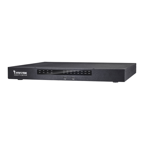
VIVOTEK - Built with Reliability Physical Description Front View 1 2 3 1 System status LED 2 Recording activity LED 3 Network uplink status/activity LED 4 HDD activity LED (#1 ~ 4) 5 USB 2.0 ports for mouse, keyboard, or joystick... - Page 14 VIVOTEK - Built with Reliability NOTE: You can also use the Reset button to restore system defaults. Press and hold down the button for longer than 5 seconds. The system should start restoring defaults. IMPORTANT: It is important to leave a clearance of 25cm behind the chassis. The clearance is required to ensure an adequate airflow through the chassis to ventilate heat.
- Page 15 VIVOTEK - Built with Reliability 2. Secure the HDD brackets to the hard drives. Label side 3. Note the locations of hard drives and the connectors on the main board. SATA Power HDD connectors SATA Data HDD positions User's Manual - 15...
- Page 16 VIVOTEK - Built with Reliability 4. Connect SATA data and power cables to the hard drives. SATA Data SATA Power SATA Power 16 - User's Manual...
- Page 17 VIVOTEK - Built with Reliability 5. Secure the hard disks to the mounting positions in the chassis with its label side facing up, and the connectors facing the inside of the chassis. The sample drawing below shows the position of drive #2.
- Page 18 VIVOTEK - Built with Reliability Rack-mounting (Optional, and the slide rails are separately purchased) IMPORTANT: If you have either a round-holed or square-holed rack, install cage nuts or clip nuts to the desired positions on the rack posts. The instructions below are based on the installation to a 4-post equipment rack.
- Page 19 VIVOTEK - Built with Reliability 3. Secure the inner rails to the sides of the chassis using the M4 screws. Locking Clip to the rear M4 x6 4. Secure the L-shape brackets to the front- and rear-ends of outer rails using the black round head screws and washers.
- Page 20 VIVOTEK - Built with Reliability Adjust the length of rails to match the rack posts. The side w/ a locking clip to the front 5. Secure the slide rails to rack posts using the #10 screws. 20 - User's Manual...
- Page 21 VIVOTEK - Built with Reliability 6. Pull the middle rails out of the slide rail assemblies. 7. Hold the chassis using both hands on the sides of the chassis. Align the tips of inner rails on the chassis with the open portion of the slide rail assemblies. Push the system into the assemblies until the system stops.
- Page 22 VIVOTEK - Built with Reliability 8. The inner rails and the rail assemblies should be locked on the way into the rack cabinet. Press the release tabs on the sides to slide the chassis into rack. Release tab 22 - User's Manual...
- Page 23 1. Connect to a monitor using an HDMI cable. VGA is also supported. 2. Connect CAT5e or better-quality Ethernet cable to the GbE Ethernet ports. For the ND9541P, another 16 cameras are connected via an Ethernet switch or PoE switches.
- Page 24 VIVOTEK - Built with Reliability ND9541P supports 32 channel recording, and the onboard 16 PoE ports supply power and data connectivity for 16 cameras. The NET2 GbE port should be used to connect another 16 cameras in a local network via a PoE switch or mid span.
- Page 25 VIVOTEK - Built with Reliability ND9541, ND9441 LAN/WAN USB 3.0 Camera 01 Camera 03 Camera 02 Camera 05 Camera 06 Camera 04 Camera 08 Camera 07 Camera 09 AC100~240V 50/60Hz, 2-1A 1. Connect to a monitor using an HDMI cable. VGA is also supported.
- Page 26 VIVOTEK - Built with Reliability NOTE: 1. Although the system supports MAC Binding, the system should be able to detect VIVOTEK's cameras within the network regardless of the presence of a DHCP server. Ideally, cameras and the NVR should reside in the same subnet. If a camera's IP is changed for some reasons, the system should be able to detect its new IP.
- Page 27 VIVOTEK - Built with Reliability Terminal Block Connections The terminal block pinouts is shown as follows: The DO pins default status is set to Normally Closed. Connect your relay or external devices’ signal wires to the system, the system will automatically detect the current signal status. You can then trigger the external devices using the DI/DO panel on the live view.
- Page 28 VIVOTEK - Built with Reliability WARNING: If you connect the NVR to a PoE port of the AW-FED series PoE switch, make sure you turn off the PoE output on that specific port using the onboard DIP switch. Otherwise, the high power output can damage the LAN port on NVR.
- Page 29 VIVOTEK - Built with Reliability Initial Configuration - via a Local Console A local console requires the following: 1. A monitor is connected via an HDMI or VGA cable. 2. A mouse and/or a keyboard are connected to the system.
- Page 30 VIVOTEK - Built with Reliability 3. All cameras detected on the network will be automatically selected. If necessary, deselect the cameras you want to exclude from the configuration. Click Continue to proceed. NOTE: 1. The maximum recording bandwidth is 2560x1920 @ 120 fps (4-CH)
- Page 31 VIVOTEK - Built with Reliability NOTE: If the need should arise, you can manuallly enter an IPv6 address to recruit a camera. Note that currently you can not search a camera with an IPv6 address in the device search panel.
- Page 32 5. An optional utility, VIVOCloud, is available through the Apple and Android App Stores. The VIVOCloud works with a server hosted by VIVOTEK for bridging and tunneling video requests between client devices and network cameras/CMS/NVR. The utility simplifies and facilitates network configuration for access across the Internet.
- Page 33 5-2. The QR code will be generated. 5-3. Open the QR code utility from your cell phone. If you already registered an account, tap LOG IN. If not, tap SIGN UP to register an account from a VIVOTEK server. User 5-4.
- Page 34 VIVOTEK - Built with Reliability 5-5. Tap the ADD DEVICES MANUALLY button. 5-6. You can then point your cell phone lens at the NVR screen (Step 5-3.) and use the SCAN QR CODES function to establish the connection. You may also manually enter the device ID.
- Page 35 VIVOTEK - Built with Reliability 5-7. The process will take several seconds to complete. 5-8. The NVR and the cameras under it will be ready for access. 6. Click the Done button. 7. Read the Trend Micro IoT Security Service licencse statement. Click the Accept button when done.
-
Page 36: Led Indicators
VIVOTEK - Built with Reliability LED Indicators ND9541P, ND9441P ND9541, ND9441 Name Behavior Definitions 1. Status LED Constant Green System is ready. Blinking Green Updating firmware or device pack. every 1 second Constant S.M.A.R.T.-related disk errors, or a configured H.D.D. -
Page 37: Power Up And Power Down
1. No storage system is completely fail-safe. Damage to data might occur due to file system corruption, operating system malfunction, virus infection, HDD component failures, and so on. Therefore, it is highly recommended to regularly back up your data, and VIVOTEK disclaims responsibilities of data loss or recovery. -
Page 38: Section One Management Over A Local Console
VIVOTEK - Built with Reliability Section One Management over a Local Console Chapter Two Introduction to the Local Console Interface Camera 01 Camera 03 Camera 02 Camera 05 Camera 06 Camera 04 Camera 07 Camera 08 Camera 09 38 - User's Manual... - Page 39 VIVOTEK - Built with Reliability By default, a live view appears on an HDMI monitor. The interface architecture of the local console is illustrated as follows: LiveView Main screen Main control portals Layout Time Search panel DI/DO Alarm search Search recording clip...
-
Page 40: How To Begin
VIVOTEK - Built with Reliability 2-1. How to Begin 1. How to access the Configuration Portal? Make sure a mouse is attached to your NVR. Move your mouse cursor, and the Configuration Portal will appear on screen. For all the configurable options available through this portal, please refer to Chapter 3 on page 54. - Page 41 VIVOTEK - Built with Reliability PTZ control panel for ordinary PTZ type PTZ control panel for joystick type PTZ Move speed config Preset points Pan/Tilt controller Focus far Focus near Zoom controller Home position Patrol button PTZ presets: If your PTZ cameras have preset locations, click on the button to unfold the preset menu.
- Page 42 VIVOTEK - Built with Reliability The Playback window will prompt, and a playback begins from the point in time you selected, e.g., 30 seconds ago. This function allows you to quickly review what has just happened. 03 - Camera 03 01 - Camera 01 2016.05.16...
- Page 43 VIVOTEK - Built with Reliability 4. How to recieve system alarm? Please refer to page 111 for how to configure system alarm triggers. When the alarm is triggered, e.g., by digital inputs or motion detection, an alarm message will prompt on the screen.
- Page 44 VIVOTEK - Built with Reliability 5. Why live view is unavailable? The default live view receives a camera's stream #1. If a camera's stream #1 is configured using MPEG-4 as the video codec, the following message will prompt. You can go to the Settings > Camera > Media > Video window to configure the video codec of stream #1 into H.264 or H.265.
- Page 45 VIVOTEK - Built with Reliability 6. How do I move to another layout page? Move your cursor to the right hand side of your screen. The page turner buttons will appear as shown below. For example, if you have 8 cameras placed on 2 2x2 layout pages, use these buttons to visit different pages.
-
Page 46: Operation On Camera View Cell
VIVOTEK - Built with Reliability 2-2. Operation on Camera View Cell 2-2-1. PTZ Panel Once you selected a camera, click on the PTZ button on a camera portal. The PTZ panel will prompt. Below are the description of its functions:... - Page 47 VIVOTEK - Built with Reliability Below is the PTZ panel that appears with ordinary PTZ cameras. List of preset positions Speed selector Focus far Focus near Zoom in Zoom out Starts patrol 1. PTZ control: Click on the arrow buttons to move towards the direction you wish to move to.
- Page 48 VIVOTEK - Built with Reliability Joystick support The joystick related operations are listed below: 1. Pan: Continuous move is supported. (joystick X-axis movement) 2. Tilt: Continuous move is supported. (joystick Y-axis movement) 3. Zoom: Continuous move is supported. To zoom in, move joystick Z-axis clockwise (or use button #2).
-
Page 49: Digital Zoom Panel
VIVOTEK - Built with Reliability 2-2-2. Digital zoom Panel Digital zoom is a function that provides digital zoom into a live video. Be sure you place your mouse cursor inside the Global view window for the zoom function to take effect. -
Page 50: Play Recording Clips Panel
VIVOTEK - Built with Reliability 2-2-3. Play Recording Clips Panel The Play Recording Clips function provides a shortcut to the latest recordings on the system. You can select 30 secs, 1 min, 3 mins, 10 mins, and 60 mins for an immediate playback. -
Page 51: Di/Do
VIVOTEK - Built with Reliability 2-2-4. DI/DO The DI/DO panel provides a glimpse of all DI and DO signal statuses from the connected cameras. You can manually trigger a digital output by clicking on its indicators. When a digital input is triggered, its status will also be indicated on the panel. -
Page 52: Right-Click Commands
VIVOTEK - Built with Reliability 2-2-6. Right-click Commands Left-click to select a camera. Right-click to display the selection menu. 1. Camera information: Click to display camera name, resolution, codec, or frame rate on the view cell. The information will display on the upper left corner of a view cell. - Page 53 VIVOTEK - Built with Reliability A time tab is displayed at the lower center of the screen. You can move your cursor to the lower center to display the time tab and the alarm panel. For the 3D counting cameras, right-click on its view cell to display the counting rule option. You can enable the display of counting lines, and the bounding boxes for detected objects.
-
Page 54: Chapter Three Configuation Using The Local Console
VIVOTEK - Built with Reliability Chapter Three Configuation Using the Local Console The Main Control Portal 3-1. Layout Move your mouse cursor across the screen to display the portal. By default, 5 typical layouts are provided for the user. They include: 1x1, 2x2, 3V, 3x3, 4x4, 1P+3, 1M+5, 1P+6, 2P+3, and 1M+12. -
Page 55: Search Recording Clips
VIVOTEK - Built with Reliability 3-3. Search recording clips 3-3-1. Time Search Click the button to start searching for recorded clips. A confirm box will prompt. Enter User name and Password to proceed. NOTE: The Search Recording button becomes the Smart Search II button with cameras that come with the Smart Motion Detection feature. - Page 56 VIVOTEK - Built with Reliability The timeline bar enables quick skimming through the recording. Its functions are described as follows: Timeline scale Control buttons Functional buttons Span of existing Current time recording indicator Buttons Description Time scale selector. Use the buttons to select the span of time displayed on the tool bar.
- Page 57 VIVOTEK - Built with Reliability The fisheye dewarp modes can be selected during a playback: e.g., 1R, 1P, 1O3R, or 1O8R. When playing the video recorded by a fisheye camera, the fisheye display options will be available on screen. You can click to select the 1O, 1P (Panoramic), 1R (Regional), or 1O3R (1 Original and 3 Regional), or 1O8R modes.
- Page 58 VIVOTEK - Built with Reliability Note that to export a video segment from the playback timeline, 1. Click on the Export button 2. Insert a USB drive formatted in the FAT format. 3. Select the "From time" by clicking on the timeline. You can also manually enter the "From time"...
-
Page 59: Alarm Search
VIVOTEK - Built with Reliability 3-3-2. Alarm Search Click on the Alarm search tab on the upper left of the Search panel screen to enter the Alarm Search window. You can specify the search criteria by selecting the devices to be involved in the Alarm search. - Page 60 VIVOTEK - Built with Reliability You can then specify the start time and end time to configure a span of time to be searched. You can also determine what alarms will be included in the search. 60 - User's Manual...
- Page 61 VIVOTEK - Built with Reliability You can select what types of triggers were associated with the recordings you want to find. When done with the selection, click on the Search button. In the sample screen below, a list of alarms is displayed, and you can click on any of them to replay the moment when the alarm was triggered.
- Page 62 VIVOTEK - Built with Reliability Use the page up and page down buttons to browse through the alarm list. Use the continuous playback button to let the system automatically play all alarm clips. The continuous play starts from the first alarm or from the alarm you currently clicked and selected. Click on the button again to stop the continuous play.
-
Page 63: Pos Search
VIVOTEK - Built with Reliability 3-3-3. POS Search Search by POS transaction: The NVR station can collect coordinated database information from a POS machine. This function provides access to the video clips associated with the sales records on the POS machine. Details of transaction can be listed on screen so that a manager can see the live view when controversial events occur. - Page 64 VIVOTEK - Built with Reliability 6. You can click on any of the search results to display the transaction data or playback the associated video. Displays Playback transaction data 7. You can export the related video if the need should arise. Make sure you select the "Include POS transaction data"...
- Page 65 VIVOTEK - Built with Reliability 8. Once expor ted, you should contact VIVOTEK's technical suppor t for a custom-made StandalonePlayer. Copy the standalone player to the same folder of your exported video. Use it to playback the exported video. 9. The transaction details will display along with the exported video.
-
Page 66: Smart Search Ii
VIVOTEK - Built with Reliability 3-3-4. Smart Search II Smart search II is available only for the newer line of cameras that come with Smart Motion detection. Smart search II has the following benefits: Faster search: Metadata is saved with videos coming from cameras running Smart Motion detection. - Page 67 2. Object information: Human-based information. If People detection is selected, only objects detected as human will be displayed as the search results. Please refer to VIVOTEK's website pages that are related to the Smart motion feature for the supported cameras.
- Page 68 VIVOTEK - Built with Reliability If you find important events, use the Export function to mark the start and end points on the timeline to export a video clip. By default, the export length varies depending on the appearance of moving objects.
-
Page 69: Smart Vca Event Search
VIVOTEK - Built with Reliability 3-3-5. Smart VCA event search This search panel enables the search for the detection results from Smart VCA analytics functions. They include: * Line crossing detection * Intrusion detection * Loitering detection * Face detection... - Page 70 * The detection line can be used as a fence boundary to know if someone has crossed the articulated line around a perimeter. Intrusion Detection VIVOTEK Intrusion Detection can be used to detect people entering or leaving a virtual area in the camera field of view. Alerted zone The applicable scenarios of this feature can be: * Detects when a person enters a bank vault or school after the office hours.
- Page 71 VIVOTEK - Built with Reliability Loitering Detection The Loitering detection can be used to detect a person of a group of people lingering in an area for longer than a preset time threshold. The applicable scenarios of this feature can be: * Detects when a pserson is loitering at a walk-up of ATM lane.
- Page 72 VIVOTEK - Built with Reliability Unattended Object Detection The Unattended Object detection can be used to detect objects intentionally or unintentionally left in scene. The applicable scenarios of this feature can be: * Detects objects placed in front of an emergency exit.
- Page 73 VIVOTEK - Built with Reliability Crowd Detection Crowd detection calculates the number of people in a specific area. When the number exceeds a preset number, an event is triggered. The applicable scenarios of this feature can be: * Detects the congestion when the number of people in a region exceeds a preset number, e.g., 10 in a waiting line.
- Page 74 VIVOTEK - Built with Reliability The Smart VCA search function can be accessed from the main portal using the Search button. When you are at the search panel, click on the Smart VCA search tab. 1. Select the cameras that generate VCA events. Select at least one camera.
- Page 75 VIVOTEK - Built with Reliability 5. The search results will display as thumbnail images. To view each short video clip, click on the thumbnail. The playback video window is located on the right. Click on the Expand/Shrink button to watch the video in a full screen.
- Page 76 VIVOTEK - Built with Reliability You may use the sort menus on the upper right to sort your search results. If using the "Sort by event type" option, events of different types will be displayed in a sussessive order. When exporting video clips, mouse over and select the small checkboxes on the thumbnails.
-
Page 77: Storyboard
VIVOTEK - Built with Reliability 3-3-6. Storyboard The Storyboard interface provides a glimpse of past recordings over a timeline. It looks and operates like doing the film editing after a film was shot. To enter the Storyboard window, click on the Storyboard shortcut on the upper-left of screen. - Page 78 VIVOTEK - Built with Reliability Mouse over the line of snapshots to display its time of recording. Click on a snapshot of your interest. The time of recording is immediately displayed on top of it. The detailed search is based on a narrow-down criteria. The search begins from a 24-hour time span, and then moving in to a 4-hour, 1-hour, 10-minutes, and 2-minutes span.
- Page 79 VIVOTEK - Built with Reliability If you find yourself in the wrong segment on the timeline, use the buttons on the upper-right of the screen to travel. The definitions of these buttons depend on the time span of your current position. For example, if you are in a 4-hour time span, the "Back to previous state button"...
- Page 80 VIVOTEK - Built with Reliability The playback window will appear. Please refer to page 56 for the operation details. 01-01 camera 2016.03.14 14:05:09 To return to the Live View window, click on the Back to Search recording clips button the Back to Liveview button on the upper-left of the screen.
-
Page 81: Export Recordings
VIVOTEK - Built with Reliability 3-4. Export recordings The Export recordings button allows users to directly select a piece of recordings by a specific camera, and export that to a USB thumb drive. Users can select one or multiple cameras, select a period of time in which the recording took place, and then click export. - Page 82 VIVOTEK - Built with Reliability 6. The Export progress will be shown. 7. When the Export process is done, select to resume another export or go back to the live view. Note that the Export process can take a long time if the time span of the selected video is very long.
-
Page 83: Settings
VIVOTEK - Built with Reliability 3-5. Settings 3-5-1. Settings - Overview Click the Settings button to start the camera and system settings window. A confirm box will prompt. Enter User name and Password to proceed. The system will default to the overview page displaying the camera connection and storage statuses. -
Page 84: Settings - Camera - Management
VIVOTEK - Built with Reliability The Camera menu provides access to Management, Recording, Media, Image, Motion detection, and PTZ settings pages. 3-5-2. Settings - Camera - Management On the camera Management page, you can configure the following: 1. Recruit or disband cameras. - Page 85 VIVOTEK - Built with Reliability For legacy cameras, the NVR supports RTSP connections since firmware release revision 2.6.x. To manually add a legacy camera, 1. Select an empty camera entry, 2. Click the Add button, 3. Select RTSP as the protocol.
- Page 86 VIVOTEK - Built with Reliability In Media > Stream managemeent page, the related Video, Audio, and stream configuration for RTSP cameras can not be edited. The RSTP cameras will be tagged. 86 - User's Manual...
- Page 87 VIVOTEK - Built with Reliability To recruit cameras: 1. Click on the Add button. A list of cameras in the same subnet will appear. 2. Click the Add button, the camera will be placed at an unoccupied position. You may also expand the menu on the side of the Add button to select a position number.
- Page 88 VIVOTEK - Built with Reliability To disband cameras: 1. Click on the Remove button. A list of cameras will appear. 2. The Remove button will turn yellow . Mouse over to the camera you want to remove, and its entry will display the Remove message.
- Page 89 VIVOTEK - Built with Reliability Network On the Network tabbed window, you can configure the network type, IP address, and the connection ports for video streaming. You can select DHCP as the method for cameras to acquire IP addresses, or you can manually configure static IPs for a single or all cameras.
- Page 90 VIVOTEK - Built with Reliability Camera position To change a camera's position on the Liveview layout, click and drag a camera to an unpopulated position. Note that you cannot swap the positions of two cameras by dragging a camera onto a position already populated by the other. Also, the camera index number on the management list is not affected by the change of positions.
-
Page 91: Settings - Camera - Recording
VIVOTEK - Built with Reliability 3-5-3. Settings - Camera - Recording Recording options On the camera Recording page, you can configure the following: 1. Configure the duration of camera events, for the concern that camera can be too frequently triggered. -
Page 92: Settings - Camera - Recording
VIVOTEK - Built with Reliability 3-5-4. Settings - Camera - Recording Recording options On the camera Recording page, you can configure the following: 1. Configure the duration of camera events, for the concern that camera can be too frequently triggered. - Page 93 VIVOTEK - Built with Reliability Recording Schedule By default, all video feeds from cameras are recorded at all time. You can modify the recording task using the schedule tool: 1. Click to select a recording condition's checkbox - 1. Continuous recording...
-
Page 94: Settings - Camera - Media
VIVOTEK - Built with Reliability 3-5-5. Settings - Camera - Media Live Auto adaptive stream: Default is enabled. The Auto adaptive stream automatically polls a video stream of a smaller resolution in order to reduce the streaming efforts. For example, when a view cell is placed in a 3x3 layout, it may not be necessary to stream the video in its full resolution. - Page 95 VIVOTEK - Built with Reliability The NVR adaptively selects to display a video stream of a different resolution when it is displaying on a smaller view cell or a full screen. By default, the Recording stream is Stream 1, which is recorded to the H.D.D.
- Page 96 VIVOTEK - Built with Reliability Click on the Recording tab to configure the Recording stream parameters. The stream here refers to the recording stream, namely, Stream 1. You can use these preset conditions to configure the resolution, image quality, frame rate, and the bandwidth consumption of the recording stream on this window.
- Page 97 VIVOTEK - Built with Reliability Video The Video window allows you to configure all video streams (the no. of stream available can be different for different models). You can configure the following: 1. Codec: video compression codec in H.265, H.264, MPEG-4, or MJPEG. Note that MPEG-4 is not supported for Liveview.
- Page 98 VIVOTEK - Built with Reliability ■ Dynamic Intra frame period High quality motion codecs, such as H.265, utilize the redundancies between video frames to deliver video streams at a balance of quality and bit rate. The encoding parameters are summarized and illustrated below. The I-frames are completely self- referential and they are largest in size.
- Page 99 VIVOTEK - Built with Reliability Smart codec effectively reduces the quality of the whole or the non-interested areas on a ■ screen and therefore reduces the bandwidth consumed. You can manually specify the video quality for the foreground and the background areas.
- Page 100 VIVOTEK - Built with Reliability As the result, the lower screen is constantly displayed in high details, while the upper half is transmitted using a lower-quality format. Although the upper half is transmitted using a lower quality format, you still have an awareness of what is happening on the whole screen.
- Page 101 VIVOTEK - Built with Reliability Audio The Audio window allows you to configure all audio codec, sampling rate, and Microphone input gains. Depending on design of the camera models, some codecs may not be available. Also, there are cameras that come without embedded mircrophones.
-
Page 102: Settings - Camera - Image
VIVOTEK - Built with Reliability 3-5-6. Settings - Camera - Image Display The Display window allows users to tune the image display options: 1. Video name: the video name is displayed on the title bar that is displayed on each view cell. - Page 103 VIVOTEK - Built with Reliability Image adjustment The Image adjustment window allows users to tune the basics about image display options: 1. Color: Select to display image as color or black and white. 2. Brightness. 3. Saturation. 4. Contrast. 5. Sharpness.
- Page 104 VIVOTEK - Built with Reliability Exposure, Focus, Privacy mask, Lens For specific image settings, refer to the camera's documentation for details. Cameras coming with different lens or zoom modules will display different configuration parameters. 104 - User's Manual...
-
Page 105: Settings - Camera - Motion Detection
VIVOTEK - Built with Reliability 3-5-7. Settings - Camera - Motion Detection Motion Detection To set up a detection window: 1. Select a camera by a single click. 2. Use the PTZ panel to move to a field of view where you want to place a detection window. -
Page 106: Settings - Camera - Ptz Settings
VIVOTEK - Built with Reliability 3-5-8. Settings - Camera - PTZ settings To configure PTZ preset positions: 1. Select a PTZ camera by a single click. 2. Use the PTZ panel to move to a field of view where you want to designate as a preset position. - Page 107 VIVOTEK - Built with Reliability To configure a patrol: 1. Click to enter the Patrol menu. Select a preset position if you want to change its position on the patrolling order. 2. Click the up and down buttons to change the position on the order, or click the remove button to disband a position from the order.
-
Page 108: Settings - Camera - Port Forwarding
VIVOTEK - Built with Reliability 3-5-9. Settings - Camera - Port forwarding You can associate an external port number to the cameras managed by the NVR. You can then configure the router, virtual server or firewall, so that the router can forward any data coming into a pre-configured port number to a network camera on the private network, and allow data from the camera to be transmitted to the outside of the network over the same path. -
Page 109: Settings - Camera - Update Firmware
VIVOTEK - Built with Reliability 3-5-10. Settings - Camera - Update firmware Prepare the camera firmware files in a USB thumb drive. Connect the thumb drive to the NVR’s USB port. Select a camera, and click the upload button. An upload panel will appear. Select the firmware file. Click the Upload button. - Page 110 VIVOTEK - Built with Reliability The Batch upload function allows you to update the firmware of multiple cameras. The firmware update can take place on up to 8 cameras at a time. The Waiting... message will display for cameras that are waiting for the update to take place.
-
Page 111: Settings-Alarm-Alarm
VIVOTEK - Built with Reliability 3-5-11. Settings–Alarm–Alarm The events reported from individual cameras' digital inputs, digital outputs, and motion detection can be accommodated in the NVR system's alarm settings. These events will then be reported or trigger corresponding actions as follows: 1. - Page 112 VIVOTEK - Built with Reliability When an alarm is triggered, a message prompt will appear on the Liveview or any configuration window. Below is a glimpse of alarm sources and alarm actions: Sources Actions System DI Video recording ►video footage...
- Page 113 VIVOTEK - Built with Reliability To create an alarm, 1. Click on the Add button You can manually enter a name for the current setting. You can enter up to 16 numeric or alphabetic characters for the name, including symbols such as [0-9][a-z][A-Z][_][ ]. You can also designate the interval between one alarm and the next triggered alarm to avoid the situation that the alarms can be too frequently triggered.
- Page 114 VIVOTEK - Built with Reliability 3. On the Trigger window, select system triggering conditions, or one or more cameras by selecting their checkboxes. The number of DI or DOs on each camera is automatically detected and displayed through individual checkboxes. The Motion detection function, if there are many detection windows configured on a camera, is all triggered by one checkbox.
- Page 115 VIVOTEK - Built with Reliability 4. On the Action window, you can select the Action type from a drop-down menu. The configuration details of each action type is discussion below. 4-1. Recording - When an event is triggered, the selected camera will record a video footage of the length defined by the pre-/post-event setting, to the NVR system.
- Page 116 VIVOTEK - Built with Reliability The Email subject and addresses can be composed of 254 characters in numeric or alphabetic characters including: [0-9][a-z][A-Z][_][ ][-][.][,][@]. You can enter the addresses of multiple recipients. Use semicolons, (;), to separate the addresses of multiple recipients.
- Page 117 VIVOTEK - Built with Reliability 4-4. FTP - Snapshots from specified cameras can be uploaded to an FTP site on the occurrence of an event. Enter the FTP site address in the dotted-decimal notation, e.g., 159.22.151.20. Enter the login name and password for the user account. You can enter a directory name you prefer on the FTP site.
- Page 118 VIVOTEK - Built with Reliability 4-5. Camera DO - A triggered alarm triggers a camera's DO, e.g., an alarm siren. 4-6. Camera pan-tilt-zoom - A PTZ capable camera can move its lens to the preset position in case of a triggered alarm. For example, a triggered sensor may indicate an area of interest has been intruded, and a camera's field of view should be moved to cover that area.
- Page 119 VIVOTEK - Built with Reliability 4-7. System DO - A triggered alarm can be used to toggle the NVR's digital output, e.g., to sound an alarm siren. 4-8. VIVOCloud app notification - A triggered alarm can be used to toggle an event notification to the VIVOCloud utility.
- Page 120 VIVOTEK - Built with Reliability 4-9. Send to CMS–An event message will display on your VAST CMS software in the event of GPS signal loss or G-sensor force exceeds configured thresholds. The triggered alarms can be found in the Alarm search panel.
- Page 121 VIVOTEK - Built with Reliability You should also configure a corresponding alarm on the VAST server. Enter the Alarm management window. Select System Event and begin your configuration. Select NVR and a triggering condition, such as the GPS diconnect, as your trigger.
- Page 122 VIVOTEK - Built with Reliability Select the triggering condition from the pull-down menu. Configure the corresponding action, and proceed with the rest of the configuration. When an event is triggered, such as GPS signal loss, or exceptional G-force is detected, an event message will prompt on screen.
- Page 123 VIVOTEK - Built with Reliability 4-10. Send video to full screen–The video feed from a related camera will be displayed on the occurrence of a triggered condition. 5. On the Schedule page, you can select to activate or de-activate alarm triggers throughout a specific timeline.
-
Page 124: Settings - Alarm - Email
VIVOTEK - Built with Reliability 3-5-12. Settings - Alarm - Email This window provides an interface where you can configure the connection to a Mail server. Via the Mail server, the system can deliver Emails containing system alarm messages to multiple receivers. -
Page 125: Settings - System - Information
VIVOTEK - Built with Reliability 3-5-13. Settings - System - Information On this window, you can configure the following: 1. Change the system name. Using a name in different languages is supported via a web console. 2. Select the UI text language. -
Page 126: Settings - System - Maintenance
VIVOTEK - Built with Reliability 3-5-14. Settings - System - Maintenance If the need arises for updating system firmware, acquire the update from VIVOTEK's technical support or download site. Locate the firmware binaries, and click the Import button. The upgrade should take several minutes to complete. -
Page 127: Settings - System - Display
VIVOTEK - Built with Reliability 3-5-15. Settings - System - Display On this page, you can configure the system to consecutively display (rotate) cameras' view cells on the Liveview window. For example, if you have 8 cameras in 2 2x2 layouts, the rotation can let you see the live views of all cameras by every few seconds. -
Page 128: Settings - System - Poe Management
VIVOTEK - Built with Reliability 3-5-16. Settings - System - PoE management When IP cameras are connected to the NVR's PoE ports, their power consumption is constantly monitored, and the power budget is displayed on the PoE management screen. The following apply to the PoE connections and PoE management: 1. - Page 129 VIVOTEK - Built with Reliability 9. The PoE automatic enlistment does not apply for cameras that come with preset credentials, namely, password-proteced. 10. The PoE port status can reflect the following situations: A. PoE enable –PoE is working (port icon displayed in green on the upper-right screen) B.
-
Page 130: Settings - System - Ups
VIVOTEK - Built with Reliability 3-5-17. Settings - System - UPS On this page, you can configure the system to gracefully shut down when UPS battery is lower than a certain level. You may also let it shut down when the estimated sustainable time is reached. -
Page 131: Settings - System - Log
VIVOTEK - Built with Reliability 3-5-18. Settings - System - Log System logs are categorized as System, Recording, User, Error, and Trend Micro IoT Security Service. To display system logs, select a range of time and click on the Search button. - Page 132 VIVOTEK - Built with Reliability 132 - User's Manual...
-
Page 133: Settings - System - Vivocloud Service
VIVOTEK - Built with Reliability 3-5-19. Settings - System - VIVOCloud service This window provides access to the VIVOCloud configuration. Please refer to page 32 for how to configure system access using the VIVOCloud functionality. User's Manual - 133... -
Page 134: Settings - System - Customer Support
With an Internet connection, users can also open the Remote access functionality. An access ID will be generated. They can send the ID to VIVOTEK's technical support for the support to remotely examine system configuration and errors. Note that you should only allow remote access when you need the technical support to access and diagnose system errors. -
Page 135: Settings - User
VIVOTEK - Built with Reliability 3-5-20. Settings - User The User window allows you to create more users, to change user password, and place limitations on users' privileges and administration rights. Up to 16 users can be created, including the default administrator. - Page 136 VIVOTEK - Built with Reliability To create or edit users, 1. Select a User group by unfolding its pull-down menu. Select either an Administrator or regular user as the user group. 2. Enter the User name and password. The max. number of characters for a user name is 64, with alphabetic and numeric characters including [0-9][a-z][A-Z][_][ ][-][.][,][@].
-
Page 137: Settings-User-Login / Logout
VIVOTEK - Built with Reliability 3. If you are creating a regular user with limited access to cameras, deselect the checkboxes by the cameras to deny the user access. 4. Click Apply to close the configuration window. Repeat the process to create more users. -
Page 138: Settings - Storage
VIVOTEK - Built with Reliability 3-5-22. Settings - Storage The storage page displays the volume information including physcial position, total capacity, used and free space, and associated commands such as Format and Delete. Since each volume contains only 1 hard drive, details information about the hard drive is also displayed on this page. - Page 139 VIVOTEK - Built with Reliability Attribute: The various attributes can vary from different HDD manufacturers. Value: Value for the currently selected attribute. Worst: Worst value acquired for that attribute. Threshold: A predefined threshold or triggering value. The threshold below which the normalized value will be considered exceeding specifications.
-
Page 140: Storage Volume Raid Levels
VIVOTEK - Built with Reliability Storage Volume RAID Levels IMPORTANT: By default, the Installation Wizard configures all disk drives into individual single-disk volumes. If you need to create RAID proteced volumes, delete these single-disk volumes to free them from the configuration. - Page 141 VIVOTEK - Built with Reliability 4. RAID5: A RAID5 volume provides a balance in performance and good fault tolerance. RAID5 stripes data and also generates error correction information (parity bits). One drive’s capacity is needed to store the error correction information from all member drives. A RAID5 volume requires at least 3 disk drives.
- Page 142 VIVOTEK - Built with Reliability To create a RAID volume: 1. Click on the Create Volume button on top of the listed disk drives. The Create Volume window will prompt 2. Select a RAID level from the pull-down menu. 142 - User's Manual...
- Page 143 VIVOTEK - Built with Reliability 3. Click to select the members for the volume. When done, click Create to begin the process. 4. Creating a RAID volume will erase all data on the member drives. A message prompt will remind you of the situation. Click Create to continue.
-
Page 144: Settings - Storage - Scheduled Backup
VIVOTEK - Built with Reliability 5. The RAID volume should be created in a short while. When a volume is created, video recording should also start immediately. Settings - Storage - Scheduled backup You can configure to backup your video recordings to an FTP server. The backup can be configured to take place at a configurable time, and with a backup bandwidth limitation. - Page 145 VIVOTEK - Built with Reliability To configure a scheduled backup, 1. Select the Scheduled backup: Enable checkbox. 2. Server: Enter the server name or IP address of the FTP server. 3. Port: Enter the port number. Default is 21. 4. Path: This the destination folder/path if different than root.
- Page 146 VIVOTEK - Built with Reliability Enable: Default is not selected. The scheduled backup function is not enabled by default. You must click to enable the configuration options. Type: Currently the NVR supports the backup to an FTP server. Enter the Static IP, domain name, and other parameters for access to an FTP server.
-
Page 147: Settings - Network
VIVOTEK - Built with Reliability 3-5-23. Settings - Network 1. The network parameters of two Ethernet ports are independent. You can attach these two Ethernet ports to different subnets, e.g., one for a network console or as a uplink; the other to a PoE switch for connecting more IP cameras. -
Page 148: Settings - Network - Ip
VIVOTEK - Built with Reliability Settings - Network - IP DHCP: Default is selected, the server obtains an available dynamic IP address assigned by the DHCP server each time the system is connected to the LAN. Manual setup: Select this option to manually assign a static IP address to the Network Camera. -
Page 149: Settings - Ddns
VIVOTEK provides Safe100.net, as a free DDNS dynamic domain name service for users who want access from the internet or a domain name service for the NVR. VIVOTEK maintains a database of product MAC addresses for the Safe100.net service, and you can apply one domain name for each NVR system. -
Page 150: Settings-Service
HTTPS encrypted connection is enabled by default. Instead of a web console, you can also access the NVR and the subordinate cameras using the iViewer and VIVOTEK's VAST software. The NVR can be managed as one of the sub-stations in a hierarchical device structure. - Page 151 VIVOTEK - Built with Reliability VAST2 auto connection NAT-traversal with OpenVPN You can select the "VAST Server with OpenVPN" option when installing the VAST server. A remote connection from NVR via a 3G/4G/LTE network can be made through an OpenVPN tunnel.
- Page 152 VIVOTEK - Built with Reliability With a remote VAST2 instance that needs to access the NVR via the Internet, you can enter its public IP address and credentials. The NVR runs an Open VPN client that makes remote connection via the RESTful (Repretational State Transfer) API (Application Programming Interface) service to a VPN server running on the remote site.
- Page 153 VIVOTEK - Built with Reliability Note that the NVR and VAST server should have a similar time setting when exchanging certificate information. Otherwise, the mutual handshake authentication process may fail. Enter the OpenVPN DNS domain name and the credentials on the NVR network service configuration page.
-
Page 154: Pos
5. Disputes between cashiers and customers can be resolved with video evidence. Note that the integration between NVR and a POS machine requires management of POS data. Please contact VIVOTEK for the supported POS machines. To configure the association with a POS machine. - Page 155 VIVOTEK - Built with Reliability For example, for an amount exceeding $2000, the number on screen is highlighted in a different color. To allow remote access from a VAST server, go to Settings > Service. Select the Allow access checkbox and provide a CMS password to allow remote access.
-
Page 156: Trend Micro Iot Security Service
VIVOTEK - Built with Reliability 3-7. Trend Micro IoT Security Service This NVR comes with the protection of TrendMicro security service against hackers with numerous forms of attacks. You can enable the service and let the service contiuously update tis virus database. - Page 157 VIVOTEK - Built with Reliability Trend Micro IoT event search You can search through the occurrences of security-related events by specifying the source: NVR or IP cameras; or the event types - Brute force attack, Cyber attack, or Quarantine events.
-
Page 158: Information
VIVOTEK - Built with Reliability 3-8. Information This window shows the revision number of the firmware running on this machine. 158 - User's Manual... -
Page 159: Section Two Management Over A Web Console
VIVOTEK - Built with Reliability Section Two Management over a Web Console There are two different interfaces on the system: 1. One is connecting mouse and keyboard, and an HDMI cable to a TV screen or monitor. The local management thus made is described in Section One of this manual. -
Page 160: Chapter Four Login And Getting Started
VIVOTEK - Built with Reliability Chapter Four Login and Getting Started 4-1. Login This is the login page on the browser. The minimum for resolution is 1280x960. If you enable the IE7 compatible mode when using the IE8 browser, please disable the compatibility function. - Page 161 VIVOTEK - Built with Reliability You may login to a different software utility by unfolding the side panel on the Login button. You can also select a different language using the Multilingual selector menu on the lower left corner of the Login screen. The functional items, menus, and dialogues will then be displayed using the selected language.
- Page 162 VIVOTEK - Built with Reliability Login options: You may also mouse over the Login button to display the login options. You can then enter the Liveview, Playback, or Settings window. The NVR system features a simple UI structure which consists of a Liveview window, a Playback utility, and a system Settings window.
- Page 163 VIVOTEK - Built with Reliability NOTE: The NVR supports plug-in-free web sessions using Chrome and Firefox browsers. Currently only 1 Live view or 1 Playback window is allowed on the web console. IMPORTANT: 1. Before operating the NVR, make sure you have properly installed hard drives and configured the storage volumes.
-
Page 164: Graphical Layout And Screen Elements - Liveview
VIVOTEK - Built with Reliability 4-2. Graphical Layout and Screen Elements - Liveview Layout Camera list Layout contents Logo & Menu Alarm panel panel Viewcell panel Once you log in, the system defaults to the Liveview page, which provides access to other configuration utilities, live view screen, and other functional panels. -
Page 165: Camera List Panel
VIVOTEK - Built with Reliability 4-2-1. Camera List Panel The camera list displays the recruited cameras by the sequential numbering order you configured in the System Settings utility. Sorting criteria Camera thumbnails Page switcher Depending on the size and screen resolution of your monitor, the snapshots of 8 cameras are displayed in this panel. - Page 166 VIVOTEK - Built with Reliability * Snapshot: the camera's image snapshot is replenished every 5 minutes. If a camera is disconnected, the last image taken will be used to represent a camera. * Camera index & Camera name: Placing the mouse cursor on top of a camera text displays the camera index number and the camera name.
-
Page 167: Layout
VIVOTEK - Built with Reliability 4-2-2. Layout By default, 5 typical layouts are provided for the user. They include: 1x1, 2x2, 3x3, 4x4, 1P+3, 1M+5, 1M+12, and 1M+31. System default is the 4x4 layout. Cameras that do not fit into the first page of a layout, say, a 3x3 layout, will be displayed on the succeeding layout pages. -
Page 168: Layout Contents
VIVOTEK - Built with Reliability 4-2-3. Layout contents A few functional buttons are available on the Layout contents page. Clears all view cells on the current layout. Full view: extends the view cells on the current layout to the full of the screen. -
Page 169: View Cell Panel
VIVOTEK - Built with Reliability 4-2-5. View Cell panel A single view cell is shown below. Each view cell contains a video stream display area, an information bar, and functional buttons at the bottom. A view cell is displayed in Normal, Focused, or Maximized mode. - Page 170 VIVOTEK - Built with Reliability A view cell attempting to connect to a network camera will look like this. If the connection attempt takes a long time, it may result from network problems or incorrect configuration with video streaming. For example, you may have configured the camera to be streaming a 5MP stream.
- Page 171 VIVOTEK - Built with Reliability Information Bar Status icon Camera index Video time Status icon Description Connected with live streaming; a single click on this icon can trigger a manual recording. Connected and recording video to system storage. Disconnected or trying to establish a connection.
- Page 172 VIVOTEK - Built with Reliability The time display format is as follows: yyyy/m/d/yyyy hh:mm:ss 2014.05.05 16:15:41 Tool Bar Buttons Buttons Description Resumes streaming. Pauses a video stream. Adds a Bookmark (that saves a short description and a one-minute footage from the current feed) Takes a snapshot.
- Page 173 VIVOTEK - Built with Reliability Tool Bar Functions in Details 1. Play and Pause buttons: These buttons pause and resume a video stream currently being played on your web browser. Note that this operation does not affect the video recording taking place between a camera and the NVR system.
- Page 174 VIVOTEK - Built with Reliability Below are two bookmarks (yellow tags) shown along with a recorded video in the Playback utility screen. Bookmarks help find and retrieve important moments in a recoded video. NOTE: Bookmarks will be erased if the user/system erases the video clips they were appended to. For example, system will recycle storage space by deleting old videos along with their bookmarks.
- Page 175 VIVOTEK - Built with Reliability 4. Clear: This button removes camera from the current view cell. The view cell will then be available for other cameras 5. Mute and Unmute: These buttons stops or resumes audio from a live stream.
- Page 176 VIVOTEK - Built with Reliability 9. Volume controller: The volume control takes effect when audio input from the network camera is available. Audio is heard only from a focused window, one that you selected by a mouse click from the Liveview panel.
- Page 177 VIVOTEK - Built with Reliability 1R (Regional view) 1R View (Single Regional View) Zoom Out Zoom In Zoom in/out & all-directional navigation control The 1R mode (or rectilinear) provides access to one image section within the hemisphere. You can zoom in or out (using the mouse wheel or PTZ panel) or travel through to other areas within the hemisphere using simple mouse clicks and drags.
-
Page 178: Ptz Panel
VIVOTEK - Built with Reliability 4-2-6. PTZ panel The PTZ panel takes effect for cameras that come with mechanical PTZ functions. It does not support digital PTZ functions. To utilize its functions, select a view cell populated by a PTZ camera, such as a speed dome. - Page 179 VIVOTEK - Built with Reliability PTZ presets: If your PTZ cameras have preset locations, click on the button to unfold the preset menu. Click on any of the preset locations to move to the area of your interest. Refer to your camera's User Manual for how to configure preset locations.
-
Page 180: Alarm Panel
VIVOTEK - Built with Reliability Auto pan/patrol controller: These buttons provides pan and patrol functions provided that preset locations have been configured on the camera. For a speed dome camera, the pan command tells the camera to continuously pan 360 degrees until it is stopped by a user command. - Page 181 VIVOTEK - Built with Reliability If an event is configured with a recording action, there will be a play button to the left of the alarm message. The alarm playback window will begin playback of a footage taken 10 seconds before the occurrence of an alarm.
- Page 182 VIVOTEK - Built with Reliability Move your cursor over an alarm with a recorded footage. The Play button will become available. The following buttons are available in the alarm playback window. Buttons Description View live video: displays the live view streaming instead of the alarm recording.
- Page 183 VIVOTEK - Built with Reliability Incoming Alarms New alarms will be indicated by the messages in bold letters, the alarm bell icons, and the increasing number of unread messages on the title bar. User's Manual - 183...
-
Page 184: Graphical Layout And Screen Elements - Search Recording Clips
VIVOTEK - Built with Reliability 4-3. Graphical Layout and Screen Elements - Search recording clips Layout contents Logo & Menu Camera list 03 - Camera 03 Calendar 2016.05.16 17:15:41 Alarm panel Playback panel The screen elements of the Playback window are described as follows:... -
Page 185: Camera List Panel
VIVOTEK - Built with Reliability 4-3-1. Camera List Panel The camera list displays the 8 recruited cameras by the sequential numbering order you configured in the System Settings window on page 83. The elements in the Camera list on a Search recording clips window are identical to those on a Liveview window. -
Page 186: Search Recording Clips Layout
VIVOTEK - Built with Reliability 4-3-2. Search Recording Clips Layout 3 types of layouts are provided for the Search recording clips window: 1x1, 2x2, and 1+3. In the Search recording clips window, users can simultaneously playback up to 4 recorded videos. -
Page 187: View Cells In Search Recording Clips
VIVOTEK - Built with Reliability 4-3-4. View Cells in Search Recording Clips The view cells in Liveview and Playback windows are similar. Their differences are listed as follows: 1. 3 simple layout types are supported as previously described. 2. The information bar displays camera index and video time information only. -
Page 188: Search Recording Clips Control Panel
VIVOTEK - Built with Reliability Search Recording Clips Control Panel Timeline slider Span of existing recording Control buttons Playback info Timeline zoomer The time slide bar enables quick skimming through the recording. Its functional buttons are described as follows: Buttons... - Page 189 VIVOTEK - Built with Reliability The time line shows the length of existing recording taken on a specific time span. You can use the timeline zoomer to scale down the span of time. For example, if the time span is reduced to 1 hour, then each section on the time line represents 15 minutes of recording.
-
Page 190: Alarm Panel
VIVOTEK - Built with Reliability 4-3-5. Alarm Panel The alarm panel displays the alarms or bookmarks recorded by the day of recording. Two additional buttons are available: Page selector and Alarm filter. Page selector Alarm filter See page 111 for how to configure alarms. -
Page 191: Calendar Panel
VIVOTEK - Built with Reliability 4-3-6. Calendar Panel Double-click on any of the existing cameras to display the Calendar panel. Days with recorded videos will be highlighted in blue regardless of the length of existing recordings that occurred on that day. You may then click on a day to begin viewing the past recordings. -
Page 192: Chapter Five System Settings
VIVOTEK - Built with Reliability Chapter Five System Settings Since revision 2.0.0.x, the System Settings pages are made identical to those on the local console. Since the Setting pages are identical, the following pages will be omitted. Please refer to page 83 for the description of System Settings via a local console. - Page 193 VIVOTEK - Built with Reliability Another difference is the ability to enter a camera or system name using languages other than English. The NVR's system name also supports the use of other lanaguages. This is only achievable through a web console.
-
Page 194: Chapter Six Operation
VIVOTEK - Built with Reliability Chapter Six Operation IMPORTANT: 1. Before operating the NVR, make sure you have properly installed hard drives and configured the storage volumes. Otherwise, you will not be able to operate most of the system's functionality. - Page 195 VIVOTEK - Built with Reliability To begin the design of your layout, 1. Select a layout pattern by a single click. The options are: 1x1, 2x2, 3x3, 4x4, 1P+3, 1M+5, 1M+12, and 1M+31, where 4x4 and 1M+12 are available for the 16-CH model.
- Page 196 VIVOTEK - Built with Reliability Placing different regional views of a fisheye camera into view cells will look like this: 1R View (Single Regional View) NOTE: Only an administrator can alter the display modes of fisheye cameras. Although ordinary users can make changes to a regional view, his changes will not be preserved after a console is re-started.
- Page 197 VIVOTEK - Built with Reliability 4. When you are done with the current layout design, i.e., the user layout 1, click Save to preserve your settings. This message prompts on the screen whenever any change is made to the current layout.
-
Page 198: Ptz And Other Screen Controls
VIVOTEK - Built with Reliability NOTE: By default, every users or administrator logs in to the Live view window to the last layout page he visited. The last layout page a user visited during the previous console becomes the default layout. - Page 199 VIVOTEK - Built with Reliability To access live view control, 1. Click on a view cell. The view cell will become a focused view cell. The streaming control buttons will be listed at the bottom of a view cell. These buttons have been discussed on page 172.
- Page 200 VIVOTEK - Built with Reliability To place bookmarks and exert screen controls, On a focused view cell, you can place a bookmark that saves a short description and a one- minute footage from the current feed. The bookmark is also displayed along with the recorded video, and therefore it is easier to look for a specific moment in time when you need to trace back for a scenario later.
-
Page 201: Audio
VIVOTEK - Built with Reliability To Activate and Deactivate PiP function, PiP is short for Picture in Picture, a function that provides digital zoom into a live video. When activated, a Global view window will appear at the lower right of the view cell as shown below. -
Page 202: Camera Properties And Controls
VIVOTEK - Built with Reliability 6-1-4. Camera Properties and Controls You can click on the underlined name entry of a camera on the camera list to open its properties window. Here you can find a short description of the camera name, address, and model name. -
Page 203: Alarm Panel
VIVOTEK - Built with Reliability 6-1-5. Alarm Panel To receive alarms from cameras, you need to configure alarm triggers in the Settings > Alarm configuration window (see page 111). Network cameras' digital inputs, digital outputs, or motion detection can all be used to detect conditions in external environments. You can configure certain kind of actions to take place in response to the alarms: such as, 1. -
Page 204: Layout View Control Buttons
VIVOTEK - Built with Reliability 6-1-6. Layout view Control Buttons When editing a user layout, you can use this button to clear all view cells of inserted cameras. This button extends the current layout to the full of the screen. -
Page 205: Search Recording Clips
VIVOTEK - Built with Reliability 6-2. Search Recording Clips The elements in the Camera list on a Search recording clips window are similar to those on a Liveview window. Please refer to page 165 for details on the Camera list panel. -
Page 206: Past Alarms And Bookmarks
VIVOTEK - Built with Reliability 6-2-2. Past Alarms and Bookmarks When you selected a day when alarms took place on a camera, the alarms will be listed on the Alarm panel. Up to 200 entries can be listed on a single page, and a max. of 1,000 entries across multiple pages. -
Page 207: Synchronous Playback
VIVOTEK - Built with Reliability Note that the bookmarks you inserted on the Liveview window will be listed on the Alarm panel, and the bookmarks will also appear on the slide bar of the Playback window. To retrieve or view the video clip tagged by the bookmark, click on it to play the video that was recorded by the time bookmark was inserted. -
Page 208: Export Media
VIVOTEK - Built with Reliability 6-2-4. Export media To export video clips, 1. Click on the Export media button on the tool bar, while the Playback window is playing a video section of your interest. 2. An Export media window will prompt. -
Page 209: Time Search
VIVOTEK - Built with Reliability 6-2-5. Time Search Use the time line slide bar to find the nearest recording from a specific point in time. Timeline slider Span of existing recording Control buttons Playback info Timeline zoomer Details of the control bar in the Playback window can be found on page 188. - Page 210 VIVOTEK - Built with Reliability Time span =12 hrs Each section =3 hrs Total time span Time span =1 hrs Each section =15 mins If recordings take place by an event-triggered recording, the intervals between recordings can be down to 1 minute, and the individual recordings will not be easily discernible. In this situation, you can mouse over the timeline to pin-point individual recording instances.
-
Page 211: Technical Specifications
VIVOTEK - Built with Reliability Technical Specifications Technical Specifications ND9441P ND9541P Model 16-CH Embedded Plug & Play NVR 32-CH Embedded Plug & Play NVR Hardware Information System Technical Specifications Embedded Linux ND9441 ND9541 Model 16-CH H.265 Embedded NVR 32-CH H.265 Embedded NVR... - Page 212 VIVOTEK - Built with Reliability Technical Specifications ND9441P ND9541P Model 16- CH Embedded Plug & Play NVR 32- CH Embedded Plug & Play NVR Memory 2 GB or above Ethenet 10/100Mbps Display Resolution 1024x768 pixels or above Web Browser Internet Explorer 10 (32 bit) or above...
- Page 213 All specifications are subject to change without notice. Copyright © VIVOTEK INC. All rights reserved. Ver. 2 User's Manual - 213 6F, No.192, Lien- Cheng Rd., Chung- Ho, New Taipei City, 235, Taiwan, R.O.C. | T: + 886- 2- 82455282 | F: + 886- 2- 82455532 | E: sales@vivotek.com | W: www.vivotek.com...
- Page 214 VIVOTEK - Built with Reliability Technology License Notice AMR-NB Standard THIS PRODUCT IS LICENSED UNDER THE AMR-NB STANDARD PATENT LICENSE AGREEMENT. WITH RESPECT TO THE USE OF THIS PRODUCT, THE FOLLOWING LICENSORS’ PATENTS MAY APPLY: TELEFONAKIEBOLAGET ERICSSON AB: US PAT. 6192335; 6275798; 6029125; 6424938; 6058359. NOKIA CORPORATION: US PAT.
-
Page 215: Safety And Compatibility
VIVOTEK - Built with Reliability Safety and Compatibility Federal Communications Commission (FCC) Statement This Equipment has been tested and found to comply with the limits for a Class A digital device, pursuant to Part 15 of the FCC rules. These limits are designed to provide reasonable protection against harmful interference when the equipment is operated in a commercial environment. - Page 216 VIVOTEK - Built with Reliability Japan VCCI Class A statement ACA (Australian Communications Authority) CAUTION RISK OF EXPLOSION IF BATTERY IS REPLACED BY AN INCORRECT TYPE. DISPOSE OF USED BATTERIES ACCORDING TO THE INSTRUCTIONS 216 - User's Manual...
Need help?
Do you have a question about the ND9541P and is the answer not in the manual?
Questions and answers