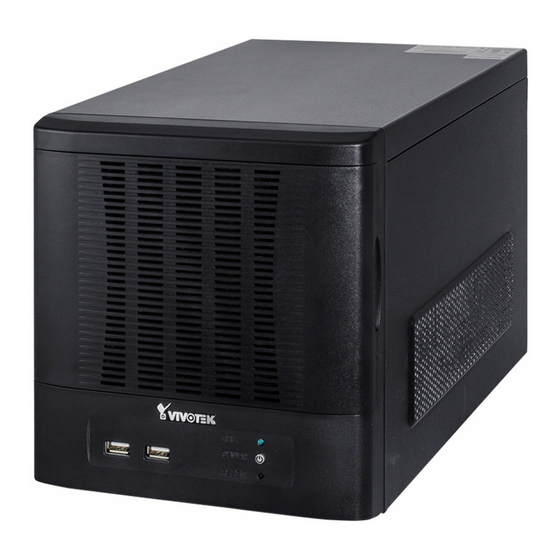
Vivotek nd8401 User Manual
Hide thumbs
Also See for nd8401:
- User manual (202 pages) ,
- Installation manual (12 pages) ,
- Quick installation manual (11 pages)
Table of Contents
Advertisement
Quick Links
Warning Before Installation
Power off the Network Video
Recorder if you detect abnormal
smell or smoke coming from it.
Do not place the Network Video
Recorder around the heat sources,
such as television or oven.
Keep the Network Video Recorder
away from direct sunlight.
Do not attempt to remove or uninstall
Nor should you open the chassis. Doing
so will void our warranty.
1
Package Contents
ND8401
Software CD
Warranty Card
Keep the Network Video Recorder
away from water. If the Video Recorder
is wet, power off immediately.
Refer to your user's manual for the
operating temperature.
Do not place the Network Video
Recorder in high humidity
environments.
Power Cord
Quick Installation Guide
Screws and Bezel Keys
EN - 1
x12
Advertisement
Table of Contents

Summary of Contents for Vivotek nd8401
-
Page 1: Package Contents
Recorder in high humidity environments. Do not attempt to remove or uninstall Nor should you open the chassis. Doing so will void our warranty. Package Contents ND8401 Power Cord Software CD Quick Installation Guide Screws and Bezel Keys Warranty Card... -
Page 2: Physical Description
Physical Description Front View Disk 1 Disk 2 Disk 3 Disk 4 HDD LED Power button & LED Reset button Rear View USB ports Fan exhaust outlet Power Switch Power Socket LAN - WAN RS-232 (reserved) Line In Line Out MIC In USB combo eSATA IMPORTANT:... -
Page 3: Hardware Installation
Hardware Installation SATA hard disk(s) are user-supplied. The network video recorder can readily accommodate most of the off-the-shelf SATA hard drives. 1. Open the front panel. 2. Use the included bezel key to unlock the bezel lock. 3. Open the drive tray bezel by flipping the bezel latch to the side. The bezel lever will spring open, and you can then remove the drive tray. - Page 4 IMPORTANT: Avoid touching the hard drive's circuit board or connector pins. Doing so can damage the hard drive by electro-static discharge. 5. Install drive tray by pushing it into drive bay. When it is almost fully inserted, close the bezel. The bezel will secure the back-end connection to the backplane. Bezel Lever 6.
- Page 5 Interface Connections 1 & 2. Connect CAT5 or better-quality Ethernet cables to cameras via a local, switched network, or clients through the Internet. Refer to next page for more information. 3. Connect the DB15 VGA port to a monitor (with resolutions up to 1920x1080). 4.
-
Page 6: Network Deployment
Network Deployment 1. Connect network cameras to the NVR’s LAN ports. 2. If you want to access NVR over the Internet, connect the NVR to the Internet via the WAN port. A web console can be established from a remote PC by keying http://<public IP>:3454 the TCP port will be necessary. - Page 7 1. Once your NVR is started, you will be prompted by the Setup Wizard. You should then installation is required. NOTE: You must install at least one hard drive the LiveClient console will not start. 2. Enter the default User name and Password as admin & admin. It is recommended you change the password later to prevent unauthorized access.
-
Page 8: Ready To Use
6. On the Camera page, all cameras connected through the local network should appear on a Camera list after a brief search. You can manually assign IP addresses by clicking on checkbox and let NVR assign IPs to cameras. Click Next to end the initial setup. Make sure you have the cameras' access credentials in order to make individual changes. - Page 9 3. 3-1. By default, the Batch Insert Cameras window will prompt for you to recruit 3-2. Click on the Search button. 3-3. Select cameras by clicking their checkboxes. 3-4. Click OK, return to the previous window, and click the Insert button. 4.


Need help?
Do you have a question about the nd8401 and is the answer not in the manual?
Questions and answers