Crane Barnes 4SHM Installation And Operation Manual
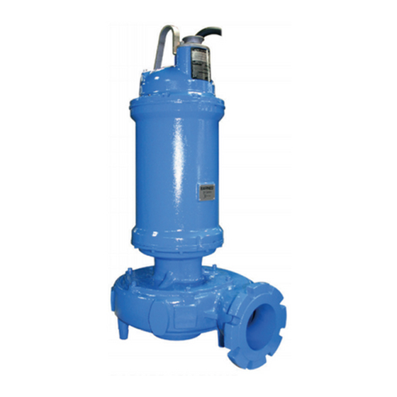
Solids handling submersible pump
Hide thumbs
Also See for Barnes 4SHM:
- Installation and operation manual (48 pages) ,
- Installation and operation manual (40 pages) ,
- Installation and operation manual (61 pages)
Table of Contents
Advertisement
INSTALLATION and OPERATION MANUAL
Solids Handling Submersible Pump
32 Frame
IMPORTANT!
Read all instructions in this manual before operating pump.
As a result of Crane Pumps & Systems, Inc., constant product improvement program,
product changes may occur. As such Crane Pumps & Systems reserves the right to
change product without prior written notification.
A Crane Co. Company
420 Third Street
Piqua, Ohio 45356
Phone: (937) 778-8947
Fax: (937) 773-7157
www.cranepumps.com
Manual Index
4SHM
Monovane Pumps
75HP, 1750RPM
4SHD
Dual Vane Pumps
75 - 100HP, 1750RPM
6SHV
Vortex Pumps
75 - 100HP, 1750RPM
50 - 75HP, 1150RPM
40HP, 870RPM
6SHM
Monovane Pumps
75 - 100HP, 1750RPM
6SHD
Dual Vane Pumps
75 - 100HP, 1750RPM
8SHVV
Vortex Pumps
50 - 100HP, 1150RPM
40 - 50HP, 870RPM
This product may be covered by one or more of the following
patents and other patent(s) pending: US Patent 8,128,360
83 West Drive, Bramton
Ontario, Canada L6T 2J6
Phone: (905) 457-6223
Fax: (905) 457-2650
8SHDU
Dual Vane Pumps
75HP, 1750RPM
8SHTM
Tri Vane Pumps
75 - 150HP, 1750RPM
50 - 100HP, 1150RPM
40 - 50HP, 870RPM
10SHD
Dual Vane Pumps
50 - 100HP, 1150RPM
40 - 50HP, 870RPM
10SHT
Tri Vane Pumps
50 - 100HP, 1150RPM
Form No. 138551-Rev. K
Advertisement
Table of Contents

Related Manuals for Crane Barnes 4SHM


Summary of Contents for Crane Barnes 4SHM
- Page 1 Read all instructions in this manual before operating pump. As a result of Crane Pumps & Systems, Inc., constant product improvement program, product changes may occur. As such Crane Pumps & Systems reserves the right to change product without prior written notification. A Crane Co. Company...
-
Page 2: Table Of Contents
START-UP REPORT ........................ 35 - 36 Other brand and product names are trademarks or registered trademarks of their respective holders. ® Barnes is a registered trademark of Crane Pumps & Systems, Inc 1995,1997,1998,1/2004, 4/05 , 1/06, 3/06, 9/06, 12/06, 2/07... -
Page 3: Safety First
IMPORTANT! - Crane Pumps & Systems, Inc. is not responsible for losses, injury, or death resulting from a WARNING! - DO NOT pump hazardous materials failure to observe these safety precautions, misuse or (flammable, caustic, etc.) unless the pump is specifically... -
Page 4: General Information
Inc., Service Department in Piqua, Ohio, telephone (937) to be installed or removed without requiring personnel to 778-8947 or Crane Pumps & Systems Canada, in Brampton, enter the wet well. Place the Break Away Fitting (BAF) in Ontario, (905) 457-6223. - Page 5 B-3) Liquid Level Controls: B-4.1) Electrical Connections: It is recommended to use a liquid level control system When the electrical connections are made, the lead wires that allows the on and off point to be separated by at least from the power cable should be stripped so that the ground twelve inches.
- Page 10 8 AWG, 6 AWG, 2 AWG 0 AWG / 18/5 - Dual Cord THREE PHASE 460-575 VOLT AC THREE PHASE 460-575 VOLT AC Power Cable Motor Lead ID Power Cable Motor Lead ID Green (Ground) Green Green (Ground) Green Black Black White White...
- Page 11 WIRING DIAGRAM FIGURE 4 B-4.3) Overload Protection: Current sensing overloads must be provided in the pump A manual momentary start switch is required to prevent control panel and should be properly sized for the full load the automatic restarting of the motor when the thermostat current of the pump.
-
Page 12: Start-Up Operation
If a panel is to be supplied locally, it is recommended that the Crane Pumps & Systems Pump Monitor Relay (P/N 134667) be used to perform the control circuit functions for the Temperature and Moisture Sensor Monitoring described in sections B4.3 and B4.4. -
Page 13: Preventative Maintenance
C-3.2) Insulation Test: 2. Check oil for contamination using an oil tester with a range to 30 Kilovolts breakdown. Before the pump is put into service, an insulation (megger) 3. If oil is found to be clean and uncontaminated (measure test should be performed on the motor. - Page 14 E-2.2) Reassembly: Stationary Member To install impeller, apply a thin film of oil to motor shaft and Polished Face Out slide impeller straight onto shaft, keeping keyways lined up. Drive key into keyway. Thread cap screw and washer into shaft and torque to 140 ft. lbs. Rotate impeller to check for binding.
-
Page 15: Replacement Parts
SECTION: F REPLACEMENT PARTS F-1 ORDERING REPLACEMENT PARTS: When ordering replacement parts, ALWAYS furnish the following information: 1. Pump serial number and date code. (Paragraph F-4) 2. Pump model number. (Paragraph F-3) 3. Pump part number. (Paragraph F-2) 4. Part description. 5. -
Page 16: Trouble Shooting
TROUBLE SHOOTING CAUTION ! Always disconnect the pump from the electrical power source before handling. If the system fails to operate properly, carefully read instructions and perform maintenance recommendations. If operating problems persist, the following chart may be of assistance in identifying and correcting them: MATCH “CAUSE”... - Page 17 DIM. ‘A’ MODEL INCHES NUMBER (MM) 3SHVC ACCESS COVER (SUPPLIED BY OTHERS) 3XSHVC 3.00 (76.2) 3SHVR 3XSHVR GUIDE RAIL CAP SUPPLIED 3SHVRA WITH BAF MODELS 3XSHVRA 3.50 (88.9) 3SHMPA INTERMEDIATE 3XSHMPA SUPPORT ASSY 4SHMS (OPTIONAL) REFER 4XSHMS 3.75 TO SECTION C-3 2"...
-
Page 18: Cross Sections (Fig. 9 & 10)
SH Pump Series - CROSS SECTIONS SH Vortex SH Enclosed FIGURE 9 FIGURE 10... - Page 19 SH Enclosed Pump Series - EXPLODED VIEWS FIGURE 11...
-
Page 20: Parts Lists
PARTS LIST Rotor Kit ......See Table on Page 28 (◊) 19B, 36 Stator Kit ......See Table on Page 28 (≈) 14, 28, 35, 38, 70 Seal Kit ......See Table on Page 26 (+) 3, 4A, 4B, 7, 9-, 19A, 53, 60 Bearing Kit .......... - Page 21 SH 32 Frame - PARTS LIST 138310 ♦ Screw, SHCS, M18 x 2.50 x 50 ● 138056 Plate, Bushing, Retainer Steel 138055 ‡ Bushing, BRZ, Oil, 2.88 Bronze 138053 □ Bracket, Bearing, 32FR Class 30 CI 134013 − Connector, Wire, Clip 138542 ♦...
- Page 22 Volute Pilot Diameter Seal Plate Kit Volute Model Volute Size Volute P/N Volute Kit P/N Seal Plate P/N O-Ring P/N Wear Ring P/N 3SHVC 208mm 3SHVR 180mm 3SHVRA 208mm 3SHMPA 208mm 4SHVA 208mm 4SHVB 208mm Not Available in 32 Frame 4SHVBA 240mm 4SHMS...
- Page 23 “E” Impeller “I” Impeller Trim Dia. Ductile Iron Nihard Trim Dia. Ductile Iron Nihard mm (in) Part No. Part No. mm (in) Part No. Part No. 370mm (14.57in) 138927 143367 370mm (14.57in) 138928 143368 365mm (14.37in) 138927TA 143367TA 365mm (14.37in) 138928TA 143368TA 360mm (14.17in)
- Page 24 “L” Impeller “M” Impeller Trim Dia. Ductile Iron Nihard Trim Dia. Ductile Iron Nihard mm (in) Part No. Part No. mm (in) Part No. Part No. 330mm (12.99in) 138931 143371 370mm (14.57in) 138932 143372 325mm (12.80in) 138931TA 143371TA 365mm (14.37in) 138932TA 143372TA 320mm (12.60in)
- Page 25 “T” Impeller “V” Impeller Trim Dia. Ductile Iron Nihard Trim Dia. Ductile Iron Nihard mm (in) Part No. Part No. mm (in) Part No. Part No. 455mm (17.91in) 138101 143294 455mm (17.91in) 138101 143294 450mm (17.72in) 138101TA 143294TA 450mm (17.72in) 138101TA 143294TA 445mm (17.52in)
- Page 26 The Following Impeller Kits Include A Wear Ring “U” Impeller “W” Impeller Trim Dia. Ductile Iron Nihard Trim Dia. Ductile Iron Nihard mm (in) Part No. Part No. mm (in) Part No. Part No. 305mm (12.00in) 138102-KIT 143293 360mm (14.17in) 138100-KIT 143295 300mm (11.81in)
- Page 27 Seal Kits Seal Kit I.B. Seal I.B. Seal O.B. Seal O.B Seal Part No. Part No. Material Part No. Material 140613 138315 Carbon / Ceramic 138315 Carbon / Ceramic 140614 (STD) 138315 Carbon / Ceramic 138315SD Silicon Carbide / Silicon Carbide 140615 138315 Carbon / Ceramic...
- Page 28 Additional Components Component Part No. Single Sale Impeller See Table Wear Ring See Table Impeller, Volute Kit Lifting Handle 138546 Seal Plate Kit, Stator Kit, Pipe Plugs 014270-SS, 127269 Bearing Bracket Kit, Motor Cap Kit Wire Tie Cable 039462 Stator Kit Nameplate No Resale Nameplate/Model Plate Rivets...
- Page 29 1750 RPM Example Rotor Kit Stator / Motor Housing Model No. Rotor Kit Stator / Motor Housing Model No. Part No. Kit Part No. Part No. Kit Part No. ─ SH ─ ─75044 140268 140269 4SHVB30092 131980 132056 ─ SH ─ ─75054 140272 140273 ─...
- Page 34 Notes...
-
Page 35: Warranty
Reliance Electric), Effluent and Sump pump models are Warranted for sixty (60) months (or 10,000 hours of operation) from the date of manufacture from Crane Pumps & Systems to the End Purchaser as follows: Crane Pumps &... -
Page 36: Returned Goods Policy
Crane Pumps & Systems, Inc. Distributor. RETURNED GOODS RETURN OF MERCHANDISE REQUIRES A “RETURNED GOODS AUTHORIZATION”. CONTACT YOUR LOCAL CRANE PUMPS & SYSTEMS, INC. DISTRIBUTOR. Products Returned Must Be Cleaned, Sanitized, Or Decontaminated As Necessary Prior To Shipment, To Insure That Employees Will Not Be Exposed To Health Hazards In Handling Said Material. -
Page 37: Start-Up Report
A Crane Co. Company START-UP REPORT General Information Pump Owner’s Name: __________________________________________________________ Address: ____________________________________________________________________ Location of Installation: _________________________________________________________ Contact Person: __________________________________Phone: _______________________ Purchased From: _____________________________________________________________ Nameplate Data Pump Model #: ___________________ Serial #: _____________________________________ Part #: __________________________ Impeller Diameter: ____________________________ Voltage: _________ Phase: _____ Ø... - Page 38 ( ) Engineer: ____________________________ ( ) Operator: ________________________ ( ) Contractor: ____________________________ ( ) Other: ___________________________ All parties should retain a copy of this report for future trouble shooting/reference A Crane Co. Company 420 Third Street 83 West Drive Piqua, Ohio 45356 Brampton, Ont.
Need help?
Do you have a question about the Barnes 4SHM and is the answer not in the manual?
Questions and answers