Advertisement
INSTALLATION, OPERATION & MAINTENANCE MANUAL
DISCONTINUED
NOT be available
IMPORTANT!
Read all instructions in this manual before operating pump.
As a result of Crane Pumps & Systems, Inc., constant product improvement program,
product changes may occur. As such Crane Pumps & Systems reserves the right to
change product without prior written notifi cation.
A Crane Co. Company
420 Third Street
Piqua, Ohio 45356
Phone: (937) 778-8947
Fax: (937) 773-7157
www.cranepumps.com
Manual Index
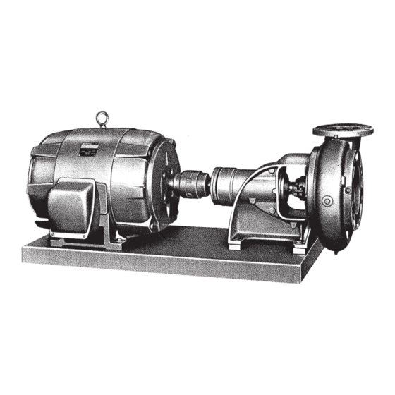
DEMING
DEMING
End Suction Centrifugal Pumps
Parts may
®
Series: 4060
Semi-Open Impeller
Series: 4160
Enclosed Impeller
83 West Drive, Bramton
Ontario, Canada L6T 2J6
Phone: (905) 457-6223
Fax: (905) 457-2650
Form No. 120002-Rev. D
Advertisement

Related Manuals for Crane DEMING 4060 Series


Summary of Contents for Crane DEMING 4060 Series
- Page 1 Read all instructions in this manual before operating pump. As a result of Crane Pumps & Systems, Inc., constant product improvement program, product changes may occur. As such Crane Pumps & Systems reserves the right to change product without prior written notifi cation.
-
Page 2: Table Of Contents
CROSS-SECTIONS & PARTS LIST ..........12 - 13 WARRANTY & RETURNED GOODS ..........15 Other brand and product names are trademarks or registered trademarks of their respective holders. Deming® is a registered trademark of Crane Pumps & Systems, Inc. 1996, 11/06 Alteration Rights Reserved... -
Page 3: Safety First
Crane Pumps & Systems, Inc. is not responsible for pressures. It is recommended that a high case temperature losses, injury, or death resulting from a failure to observe switch or pressure relief valve be installed on the pump body. -
Page 4: General Information
Systems Service Department in Piqua, Ohio, telephone Adjust the metal supports or wedges until the shafts of (937) 778-8947 or Crane Pumps & Systems Canada, Inc., the pump and driver are level. Check the coupling faces, Bramton, Ontario, (905) 457-6223. - Page 5 3. FIELD ALIGNMENT The faces of the coupling halves should be spaced far enough apart so that they cannot strike each other when the driver rotor is moved toward the pump. The necessary ANGULAR tools for checking the alignment of a fl exible coupling are a MISALIGNMENT straight edge and a taper gauge or a set of feeler gauges.
- Page 6 Figure 4 5. PIPING NOTE: A gate valve in the suction piping should not be The pump suction and discharge connections are not used as a throttling device, as this may cause the liquid to intended to indicate the required suction and discharge overheat during operation.
-
Page 7: Operation
C - OPERATION 2. STARTING THE PUMP On initial start up, the gate valve in the discharge piping should be closed and slowly opened after pump is up to The following important items should be checked as pump speed and pressure developed. DO NOT operate pump for is started and placed in operation. - Page 8 f. Reassemble shaft coupling. Place pump in CAUTION: DO NOT over grease bearings or operation and check power required to be certain add excess oil impeller does not rub casing. The following lubricants are recommended at the operating NOTE: The Fig. 4160 Series with enclosed impeller temperature indicated: normally does not require adjustment of the impeller.
- Page 9 a. Disconnect power supply to the motor and remove a. Inspect bearings and replace if worn. motor from baseplate or remove coupling spacer if b. Press grease retainer (51) onto shaft to position spacer type coupling is installed. marked. Press bearing (16) onto shaft until inner b.
- Page 10 Apply light oil to the inside of the seal bellows and ITEM No DESCRIPTION to the shaft sleeve (14) then slide seal gland (251), Packing Box Cover gland gasket (259) and rotating seal assembly (89B) onto the shaft sleeve. See Figure 5. Shaft Sleeve m.
-
Page 11: Locating Trouble
E - LOCATING TROUBLE 5. Pump Takes Too Much Power a. Speed too high - Compare Pump and motor 1. No Liquid Delivered nameplates a. Pump not primed - See Priming b. Head lower than rating - pumps too much liquid. b. -
Page 12: Cross-Sections & Parts List
FIG. 4060 SERIES END SUCTION Semi-Open Impeller, Packed Stuffi ng Box, Grease Lubricated Bearings ITEM No. DESCRIPTION ITEM No. DESCRIPTION ITEM No. DESCRIPTION Casing Grease Retainer *270 Impeller Washer Impeller Lockwasher *272 Impeller Screw O-ring Shaft Casing Gasket Jack Screw Packing Box Cover Adjusting Locknut (*) Recommended Spare Parts... - Page 13 FIG. 4160 SERIES END SUCTION Enclosed Impeller, Packed Stuffi ng Box, Grease Lubricated Bearings ITEM No. DESCRIPTION ITEM No. DESCRIPTION ITEM No. DESCRIPTION Casing Grease Retainer Pipe Plug Impeller Lockwasher Pipe Plug Shaft Casing Gasket *270 Impeller Washer Wear Ring Set Screw *272 Impeller Screw O-ring...
-
Page 15: Warranty & Returned Goods
Crane Pumps & Systems, Inc. Distributor. RETURNED GOODS RETURN OF MERCHANDISE REQUIRES A “RETURNED GOODS AUTHORIZATION”. CONTACT YOUR LOCAL CRANE PUMPS & SYSTEMS, INC. DISTRIBUTOR. Products Returned Must Be Cleaned, Sanitized, Or Decontaminated As Necessary Prior To Shipment, To Insure That Employees Will Not Be Exposed To Health Hazards In Handling Said Material. - Page 16 A Crane Co. Company START-UP REPORT General Information Pump Owner’s Name: __________________________________________________________ Address: ____________________________________________________________________ Location of Installation: _________________________________________________________ Contact Person: __________________________________Phone: _______________________ Purchased From: _____________________________________________________________ Nameplate Data Pump Model #: ___________________ Serial #: _____________________________________ Part #: __________________________ Impeller Diameter: ____________________________ Voltage: _________ Phase: _____ Ø...
- Page 18 Notes...
Need help?
Do you have a question about the DEMING 4060 Series and is the answer not in the manual?
Questions and answers