Table of Contents
Advertisement
Quick Links
Advertisement
Table of Contents

Subscribe to Our Youtube Channel
Related Manuals for Motorline professional TELICA


Summary of Contents for Motorline professional TELICA
- Page 1 TELICA USER’S AND INSTALLER’S MANUAL V3.2 REV. 05/2020...
-
Page 2: Table Of Contents
00. CONTENT 01. SAFETY INSTRUCTIONS INDEX ATTENTION: 01. SAFETY INSTRUCTIONS This product is certified in accordance with European 02. THE PACKAGE Community (EC) safety standards. INSIDE THE PACKAGE 03. OPERATOR This product complies with Directive 2011/65/EU of the DIMENSIONS European Parliament and of the Council, of 8 June 2011, on TECHNICAL SPECIFICATIONS the restriction of the use of certain hazardous substances in 04. -
Page 3: Safety Instructions
01. SAFETY INSTRUCTIONS GENERAL WARNINGS the motorized door or gate from being triggered involuntarily. • This manual contains very important safety and usage information. WARNINGS FOR TECHNICIANS very important. Read all instructions carefully before beginning the installation/usage procedures and keep this manual in a safe place •... - Page 4 01. SAFETY INSTRUCTIONS use or maintenance! to the release mechanism. • Safety norms are not followed in the installation, use and • Disconnect means, such as a switch or circuit breaker on the electrical panel, must be provided on the product’s fixed power supply leads in maintenance of the product.
-
Page 5: The Package
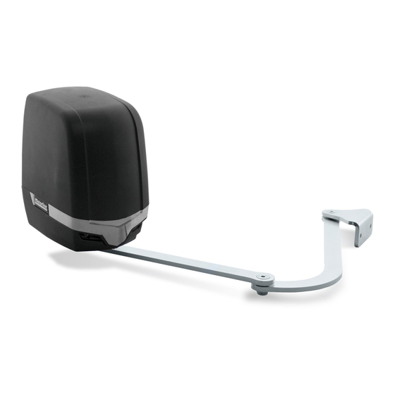
02. THE PACKAGE 03. OPERATOR INSIDE THE PACKAGE DIMENSIONS The dimensions of the TELICA automation are the following: Components on the 2 motor's package: Components on the 1 motor's package: 01 • 02 articulated motors 01 • 01 articulated motor 02a •... -
Page 6: Installation
QUOTA B • Horizontal distance between the center of the hinge and the center of the motor shaft. Fig. 5 stáculo. SUPPORTS INSTALLATION EXTERNAL UNLOCK The kit exemplified below is not included in the TELICA Kit. Security Fig. 9 1 • Drill holes for M8 screw anchors. CSV100... -
Page 7: Automatism Installation 6A
04. INSTALLATION 04. INSTALLATION AUTOMATISM INSTALLATION MICROS ADJUSTMENT Remove the automation's cover. To do this, loosen the two front screws, slightly tilt Fig. 15 the cover back and pull up. 1 • Place the motor on the support plate and Fig. -
Page 8: Installation Map
04. INSTALLATION INSTALLATION MAP WARNING MOTOR LAMP ANTENNA SELECTOR EXTERIOR PHOTOCELLS JUNCTION BOX EXTERIOR INTERIOR PHOTOCELLS PHOTOCELLS GATE STOPPER LEGEND: Connection cables Fig. 23 It is important to use mechanical stoppers in the opening and closing position of the gate. It is important to use junction boxes for connections between motors, components and If not respected, components of the automation may suffer efforts for which they were not control unit. -
Page 9: Motor Connections
06. COMPONENTS TEST 05. CONNECTION SCHEME 230V MOTOR 230V MOTOR To detect if the malfunction is on the control board or on the motor is, sometimes, necessary to perform tests with connection directly to a 230Vac power supply. For this, it is necessary to interpose a capacitor on the connection in order to the automatism to work (check the type of capacitor to be used in the product manual). -
Page 10: Motor
07. MAINTENANCE 24V MOTOR MAINTENANCE To detect which are the components with problems in a 24Vdc TELICA automatism instalation, it's some- times necessary to run a test directly to a external power supply (another 24Vdc battery). • CHECK MOTOR SUPPORTS The diagram below shows how to connect the motor to the battery. - Page 11 08. TROUBLESHOOTING INSTRUCTIONS FOR FINAL CONSUMERS INSTRUCTIONS FOR SPECIALIZED INSTALLERS Anomaly Procedure Behavior Procedure II Discovering the origin of the problem • Motor • Make sure you • Still not working • Consult a qualified 1 • Open control box and checkif it has 230Vac/24Vdc power supply; MOTORLINE technician.
- Page 12 09. CONNECTION SCHEME 230V MOTOR Antenna * For more informations, check the manual Pedestrian of the photocells Opening to be installed. (1 leaf) Exterior Interior Photocells* Photocells* Close the circuit with bridge (shunt) Complete when the Opening photocells circuit (2 leaves) is not being used! Lock ∑...
- Page 13 09. CONNECTION SCHEME 24V MOTOR...
Need help?
Do you have a question about the TELICA and is the answer not in the manual?
Questions and answers