Table of Contents
Advertisement
Quick Links
Advertisement
Table of Contents

Subscribe to Our Youtube Channel
Related Manuals for Motorline professional KAPV100


Summary of Contents for Motorline professional KAPV100
- Page 1 KAPV100 USER'S / INSTALLER'S MANUAL V2.0 REV. 02/2022...
-
Page 2: Table Of Contents
00. CONTENT 01. SAFETY INSTRUCTIONS INDEX STANDARDS TO FOLLOW 01. SAFETY INSTRUCTIONS This product is certified in accordance with European STANDARDS TO FOLLOW Community (EC) safety standards. 02. CONNECTIONS SCHEME GENERAL SCHEME This product complies with Directive 2011/65/EU of the PREVIOUS INSTRUCTIONS FOR RADAR AND PHOTOCELL CONNECTIONS European Parliament and of the Council, of 8 June 2011, on PHOTOCELL MODULE SCHEME (MR28 OR CR10MS/PHOTO19A) -
Page 3: Safety Instructions
01. SAFETY INSTRUCTIONS 01. SAFETY INSTRUCTIONS GENERAL WARNINGS the motorized door or gate from being triggered involuntarily. • This manual contains very important safety and usage information. WARNINGS FOR TECHNICIANS very important. Read all instructions carefully before beginning the installation/usage procedures and keep this manual in a safe place •... - Page 4 01. SAFETY INSTRUCTIONS 01. SAFETY INSTRUCTIONS to the release mechanism. use or maintenance! • Disconnect means, such as a switch or circuit breaker on the electrical • Safety norms are not followed in the installation, use and panel, must be provided on the product’s fixed power supply leads in maintenance of the product.
-
Page 5: Connections Scheme
02. CONNECTIONS SCHEME 02. CONNECTIONS SCHEME GENERAL SCHEME PREVIOUS INSTRUCTIONS FOR RADAR AND PHOTOCELL CONNECTIONS CONNECTIONS: On the KAPV connection board there are two groups of connectors for radars and photocells: PROGRAM Grey → SELECTOR ELECTRIC LOCK Brown → RADAR INT → Connection of devices installed inside the Orange →... - Page 6 02. CONNECTIONS SCHEME 02. CONNECTIONS SCHEME PHOTOCELL MODULE SCHEME (MR28 OR CR10MS/PHOTO19A) SCHEME - 2 RADARS M1601 LOCK 15V GND REX RIN SIG PUL COM PED PED MR28 PHOTOCELLS MODULE RECEIVER CONNECTIONS: 6 5 4 3 2 1 Mód. nº1 →...
-
Page 7: Scheme - 2 Radars Mr30 With 5 Wires 6A
02. CONNECTIONS SCHEME 02. CONNECTIONS SCHEME SCHEME - 2 RADARS MR30 WITH 5 WIRES SCHEME - 2 RADARS MR30 WITH 6 WIRES MR30 (EXTERIOR RADAR) MR30 (EXTERIOR RADAR) CONNECTIONS: CONNECTIONS: Black → Black → 15V GND REX RIN SIG PUL COM PED PED 15V GND REX RIN SIG PUL COM →... -
Page 8: Scheme - 2 Radars Rap100S
02. CONNECTIONS SCHEME 02. CONNECTIONS SCHEME SCHEME - 2 RADARS RAP100S SCHEME - MB18 , SINTACT OR MB17 MB18 (TOUCH SENSOR) RAP100S (EXTERIOR RADAR) 15V GND REX RIN SI CONNECTIONS: Sensor Cable Connection CONNECTIONS: Black → Cable Extension Board 15V GND REX RIN SIG PUL COM PED PED RECEIVE →... -
Page 9: The Door
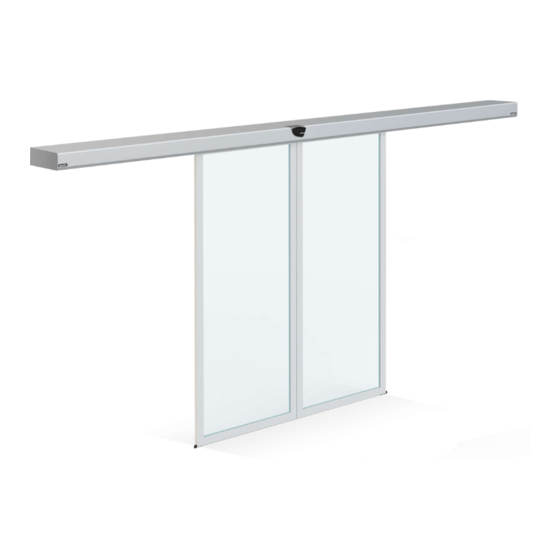
03. THE DOOR 03. THE DOOR TECHNICAL CHARACTERISTICS TECHNICAL CHARACTERISTICS With its automatic sliding system, the glass door KAPVSP is the perfect solution for the acess You can find on the door the following components: of buildings where you want constant sound and climate isolation. This door is designed for A •... -
Page 10: Measures 9A
03. THE DOOR 03. THE DOOR MEASURES MEASURES • STANDARD GRIPPER • TIGHTENING GRIPPER • GLASS FOR STANDARD GRIPPER • GLASS FOR TIGHTENING GRIPPER Standard gripper • To allow the gripper to hold the glass, it is required to make the holes as Tightening gripper •... -
Page 11: Installation
03. THE DOOR 03. THE DOOR MEASURES UNLOCK • GLASS WITH ALUMINUM FRAME (MOBILE) • ELETRIC LOCK Leaf width The electric lock is a security system that creates an automatic lock of the glass doors thus preventing burglary and increasing the safety of the space. Leaf Width: 45mm 45mm... -
Page 12: Safe Installation 11A
04. INSTALLATION 04. INSTALLATION SAFE INSTALLATION SAFE INSTALLATION 01.A 05. When using a standard gripper, slide the 06. Apply the nylon washers in the existing gripper's cover to acess the holes. 01. Place the safe under a protective material (card). Lift the safe's cover and slide it holes of the glass. - Page 13 04. INSTALLATION 04. INSTALLATION SAFE INSTALLATION SAFE INSTALLATION Full Measure A Glass Safe inferior upper limit limit Floor 11. Also on the ground, touch the glass (with the gripper already on place) to the safe. Take the full measure of the glass lower limit to the upper limit of the safe. Keep 14.
- Page 14 04. INSTALLATION 04. INSTALLATION SAFE INSTALLATION SAFE INSTALLATION 1 mm 25.A 24. Use the thread again so that the 25. Pull the anti-derailment plates upwards, cart go up together with the door. THE so that it is 1 mm of the profile as in figure 25.A.
- Page 15 04. INSTALLATION 04. INSTALLATION GLASS INSTALLATION IN SAFE GLASS INSTALLATION IN SAFE 03. Use once again the screw y to the cart rises along with the door. The PROBLEM PROBLEM glass should be between 8 and 10 mm from the ground. The utilization of a level is recommended!
-
Page 16: Guides Installation 15A
04. INSTALLATION 04. INSTALLATION GUIDES INSTALLATION STOPPERS ADJUSTMENT WALL Measure x FLOOR 28. Take the measurement between the glass 29. Take the same measurement to the glass's and the upper part of the glass (under the lower limit. gripper). 34 and 35. Make a complete manual opening to check for obstacles during opening / closing and if the course is fully made. - Page 17 04. INSTALLATION 04. INSTALLATION COMPONENTS BATERRIES After installing the motors and glasses, proceed to the installation of all the extra components The automatic glass door has 3 batteries of 12V each, connected in series (36V connection). that are in the order. These may include: These batteries are an important safety element to make the opening in case of power failure.
-
Page 18: Programming
05. PROGRAMMING 05. PROGRAMMING CONTROL BOARD CONTROL BOARD PRE-PROGRAMMING CAUTIONS • CONTROL BOARD DESCRIPTION The parameters selected in the control device are available after the door makes a fully open Indication LED It indicates the control board's power supply. and close maneuver (path recognition). Start button After pressing this button, the door will open. -
Page 19: Control Board 17A
05. PROGRAMMING 05. PROGRAMMING CONTROL BOARD CONTROL BOARD - INTERLOCK FUNCTION LATERAL A The control board allows the interconnection of two automatic glass doors through the in- • terlock function (door with interlocking). With this feature, when a door opens, the other remains closed until the first is completely closed. - Page 20 05. PROGRAMMING 05. PROGRAMMING SELETOR SELECTOR Com os comandos do seletor, pode controlar o automatismo para realizar as seguintes ações: Change the selector's function in "Free Mode": 1. Always Closed: In "free" mode, you can select the desired function by pressing it for 5sec, without having to put the password.
-
Page 21: Maintenance
06. MAINTENANCE 06. MAINTENANCE BELT OTHER INFORMATION • BELT TENSION ADJUSTMENT • VERIFICATIONS A long period of door maneuvers can lead to an alteration on the belt tension. For this rea- It is recommended a full periodic check to ensure the normal operation of the door. This son it is recommended a belt tension periodic review to ensure the normal operation of the review can only be performed by qualified technicians in handling automatic glass doors. -
Page 22: Troubleshooting
07. TROUBLESHOOTING MALFUNCTION DIAGNOSIS Problems Causes Solutions 1. Power failure. Make sure the door is receiving power supply. 2. Door stuck. Separate the door from the belt and check if the leaves move by hand without any problem. The door does not move. 3.
Need help?
Do you have a question about the KAPV100 and is the answer not in the manual?
Questions and answers