Oriental motor BLE Series Operating Manual
Brushless motor and driver package
Hide thumbs
Also See for BLE Series:
- Operating manual (52 pages) ,
- User manual (164 pages) ,
- Installation & connection manual (40 pages)
Advertisement
O P E R AT I N G M A N U A L
Brushless Motor and Driver Package
BLE Series
Introduction
„ Before use
Only qualified personnel of electrical and mechanical engineering should
work with the product.
Use the product correctly after thoroughly reading the section "Safety
precautions." In addition, be sure to observe the contents described in
warning, caution, and note in this manual.
The product described in this document has been designed and manufactured
to be incorporated in general industrial equipment. Do not use for any other
purpose. Oriental Motor Co., Ltd. is not responsible for any damage caused
through failure to observe this warning.
„ Operating Manuals for the product
Operating manuals for the BLE Series FLEX RS-485 communication type are
listed below. Read the manuals carefully before using your BLE Series FLEX
RS-485 communication type.
• BLE Series FLEX RS-485 communication type OPERATING
MANUAL (this document)
This manual explains the motor functions as well as installation method, and
others.
• BLE Series FLEX RS-485 communication type USER MANUAL
This manual explains the function, installation/connection method, operating
method of the motor and driver as well as detailed information for using the
product. The USER MANUAL does not come with the product.
Check the USER MANUAL for details on the product.
For details, contact your nearest Oriental Motor
sales office or download from Oriental Motor Website
Download Page.
Safety precautions
The precautions described below are intended to prevent danger or injury
to the user and other personnel through safe, correct use of the product.
Use the product only after carefully reading and fully understanding these
instructions.
Handling the product without observing the
instructions that accompany a "WARNING"
WARNING
symbol may result in serious injury or death.
Handling the product without observing the
instructions that accompany a "CAUTION"
CAUTION
symbol may result in injury or property damage.
The items under this heading contain important
handling instructions that the user should
Note
observe to ensure the safe use of the product.
HM-5143-4
RS-485 communication type
(Motor)
(Driver)
Thank you for purchasing an Oriental Motor product.
This Operating Manual describes product handling procedures and
safety precautions.
•Please read it thoroughly to ensure safe operation.
•Always keep the manual where it is readily available.
General
• Do not use the product in a place exposed to explosive, flammable or
corrosive gases or water splashes or near combustible materials. Doing so
may result in fire, electric shock or injury.
• Only qualified and educated personnel should be allowed to perform
installation, connection, operation and inspection/troubleshooting of the
product. Handling by unqualified personnel may result in fire, electric
shock, injury or equipment damage.
• Do not move, install, connect or inspect the product while the power is
supplied. Perform these operations after turning off the power. Failure to
observe these instructions may result in electric shock.
• The terminals on the driver front panel marked with
the presence of high voltage. Do not touch these terminals while the power
is on. Doing so may result in fire or electric shock.
• Do not use a standard type motor (not equipped an electromagnetic brake)
in a vertical application. If the driver protective function is activated, the
motor will stop and the moving part of the equipment may drop, thereby
causing injury or equipment damage.
• Do not use the brake mechanism of the electromagnetic brake motor as a
safety brake. It is intended to hold the moving parts and motor position.
Doing so may result in injury or damage to equipment.
• If the driver protective function has been activated, remove the cause and
reset the protective function. Continuing to operate the equipment without
removing the cause of problem will lead to a motor or driver malfunction,
resulting in injury or equipment damage.
Installation
• The motor and driver are Class I equipment.
When installing the motor and driver, connect their Protective Earth
Terminals. Failure to do so may result in electric shock.
• Install the motor and driver in an enclosure. Failure to do so may result in
electric shock or injury.
Connection
• Securely connect the cables in accordance with the connection examples.
Failure to do so may result in fire or electric shock.
• Do not forcibly bend, pull or pinch the cables. Doing so may result in fire or
electric shock.
• Do not machine or modify the motor cable or connection cable. Doing so
may result in electric shock or fire.
• Be sure to observe the specified cable sizes. Use of unspecified cable sizes
may result in fire.
• Observe the specified screw tightening torque when connecting terminals
to the terminal block. Failure to do so may result in electric shock or
equipment damage.
Operation
• Use a specified motor, gearhead and driver combination. Failure to do so
may result in fire, electric shock or equipment damage.
• Always keep the power supply voltage of the driver within the specified
range. Failure to do so may result in fire or electric shock.
• When using the electromagnetic brake motor, do not turn the MB-FREE
input ON while a load is held in vertical direction. Otherwise, the holding
power of the motor and electromagnetic brake will be lost, causing personal
injury or damage to equipment.
WARNING
symbol indicate
1
Advertisement
Table of Contents

Subscribe to Our Youtube Channel
Related Manuals for Oriental motor BLE Series


Summary of Contents for Oriental motor BLE Series
- Page 1 Operating manuals for the BLE Series FLEX RS-485 communication type are the presence of high voltage. Do not touch these terminals while the power listed below. Read the manuals carefully before using your BLE Series FLEX is on. Doing so may result in fire or electric shock.
-
Page 2: Precautions For Use
• When using the electromagnetic brake motor in vertical drive (gravitational • The motor surface temperature may exceed 70 °C (158 °F) operation), be sure to operate after checking the load condition. If a load in even under normal operating conditions. If the operator is excess of the rated torque is applied or the small torque limiting value is set, allowed to approach a running motor, attach a warning label the load may fall. - Page 3 • Note on connecting a power supply whose positive terminal is z Standard type • grounded • Combination type • parallel shaft gearhead The data edit connector (CN3), I/O signal connectors (CN5/CN6) and RS-485 communication connectors (CN7/CN8) on the driver are not Gearhead Driver model Model...
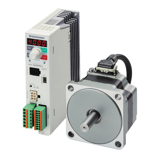
- Page 4 „ Names and functions of parts z Motor (Example: Electromagnetic brake type) • Motor Pilot Output shaft Protective Earth Terminal Mounting hole (4 locations) Motor cable Motor power connector Electromagnetic brake connector Motor signal connector Driver front face Driver bottom face Mounting holes (locations at the back) PWR/ALM LED C-DAT/C-ERR LED...
- Page 5 Name Description •SW3-No.1: Not used. (Keep this switch in the OFF position.) •SW3-No.2: Not used. (Keep this switch in the OFF position.) •SW3-No.3: This switch is used to select the power supply for I/O signals (use the built-in power supply or external power supply). To control the operation using relays and switches, set the Function setting switch1 SW3-No.3 to the ON side to select the built-in power supply.
-
Page 6: Installation
Removing/Installing the gearhead Installation To replace the gearhead or change the cable outlet direction, remove the screws assembling the gearhead. The gearhead can be removed and the motor „ Installation location cable position changed to a desired 90° direction. Install them in a well-ventilated location that provides easy access for 1. -
Page 7: X84; Installing The Round Shaft Type
Removing/Installing the gearhead z Output shaft shape • To replace the gearhead or change the cable outlet direction, remove the Combination type • parallel shaft gearhead screws assembling the gearhead. The gearhead can be removed and the motor A key slot is provided on the output shaft of each combination type parallel cable position changed to one of three 90°... -
Page 8: X84; Permissible Radial Load And Permissible Axial Load
„ Permissible radial load and permissible axial load z Stepped load shaft • Make sure the radial load and axial load received by the motor, gearhead Secure the retaining ring to the load shaft by tightening the hexagonal socket output shaft will not exceed the allowable values shown in the table below. head screw over a spacer, flat washer and spring washer. - Page 9 z Mounting to DIN rail • z Round shaft type • Use a separately sold DIN rail mounting plate (model number: PADP03) and Distance from output shaft end attach it to a 35 mm (1.38 in.) wide DIN rail. After installation, fix the both of motor and permissible radial sides of the driver with the end plate (not supplied).
- Page 10 Connection „ Connection example (electromagnetic brake motor) Electromagnetic brake connector Connect to CN1 ∗1 Motor signal connector Connect to CN4 Grounding Connection cable ∗2 Motor cable Input signals Protective Earth Terminal Connect to CN5 Be sure to ground. Motor power connector Connect to CN2 24 VDC power supply...
- Page 11 „ Selecting a power supply for I/O signals „ Grounding When installing the motor and driver, connect their Protective Earth The driver comes with a built-in power supply. Terminals To control the operation using relays and Two Protective Earth Terminals are provided on the driver.
- Page 12 „ Test operation mode „ Connecting an external speed setter Once a main power supply and 24 VDC power supply are connected, the The rotation speed can be set using an external potentiometer (supplied) or connection status can be checked by driving the motor tentatively without external DC voltage.
-
Page 13: Operation
„ Transmission rate Setting the communication The transmission rate can be set using the transmission rate setting switch (SW4). • Driver front face The transmission rate to be set should be the same as the transmission rate of the master device. Address number setting switch Factory setting: 7 (Network converter) - Page 14 STOP-MODE NETC01-M3 (MECHATROLINK-Ⅲ compatible) input NETC01-ECT (EtherCAT compatible) When the BLE Series FLEX RS-485 communication type is used in a When using the motor in vertical drive (gravitational Note CC-Link system or MECHATROLINK system, EtherCAT system while operation), although it depends on the load condition, if...
- Page 15 „ Data setter MANUAL. Since the compliance of the final machinery with the EMC The data setter lets you set data and parameters for your BLE Series FLEX Directive will depend on such factors as the configuration, wiring, layout and RS-485 communication type with ease and also functions as a monitor.
- Page 16 • Unauthorized reproduction or copying of all or part of this manual is prohibited. • Oriental Motor shall not be liable whatsoever for any problems relating to industrial property rights arising from use of any information, circuit, equipment or device provided or referenced in this manual.
Need help?
Do you have a question about the BLE Series and is the answer not in the manual?
Questions and answers