Advertisement
Quick Links
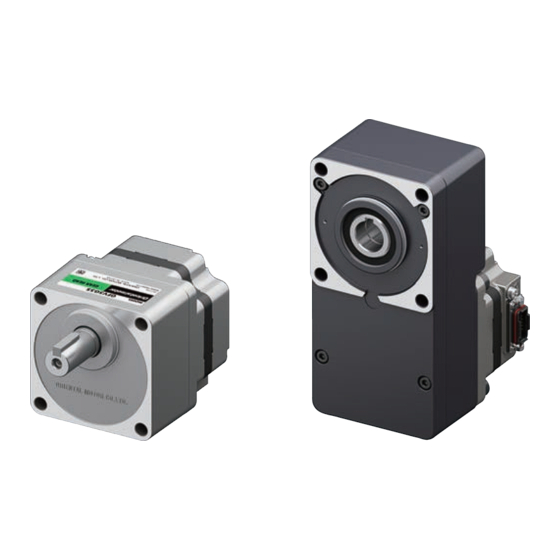
BLM Motors
OPERATING MANUAL
Thank you for purchasing an Oriental Motor product.
This Operating Manual describes product handling procedures and safety precautions.
• Please read it thoroughly to ensure safe operation.
• Always keep the manual where it is readily available.
• Only qualified personnel of electrical and mechanical engineering should work with the product.
• Use the product correctly after thoroughly reading the section "Safety precautions. "
In addition, be sure to observe the contents described in warning and caution in this document.
• The product described in this document is designed and manufactured to be incorporated in general
industrial equipment.
Do not use it for any other purpose.
Oriental Motor Co., Ltd. is not responsible for any compensation for damage caused through failure to
observe this warning.
HM-5288
Advertisement

Related Manuals for Oriental motor BLM


Summary of Contents for Oriental motor BLM
- Page 1 • The product described in this document is designed and manufactured to be incorporated in general industrial equipment. Do not use it for any other purpose. Oriental Motor Co., Ltd. is not responsible for any compensation for damage caused through failure to observe this warning.
- Page 2 Table of contents Verify the model name of the purchased product against the model shown on the nameplate. Safety precautions ....... 3 Hollow shaft flat gearheads ..23 Precautions for use ...... 4 Lists of combinations ..... 23 Names of parts ......... 25 Checking the product ....
- Page 3 1. Safety precautions Table of contents The precautions described below are intended to ensure the safe and proper use of the product and to prevent the user and other personnel from exposure to the risk of injury. Use the product only after carefully reading and fully understanding these instructions. When using the electromagnetic brake motor in a vertical drive application such as elevating Description of signs equipment, be sure to check the load condition sufficiently before operating.
- Page 4 2. Precautions for use Table of contents This chapter covers restrictions and requirements the user should consider when using the product. „ Operations Be sure to match the motor output power to the driver output power. z Use an electromagnetic brake motor in a vertical drive application such as elevating equipment.
- Page 5 3. Checking the product Table of contents Package contents Information about nameplate Verify that the items listed below are included. Tell us the model name, product serial number, and manufacturing date when you contact us. Report any missing or damaged items to the branch or sales office from which you purchased the product. The position describing the information may vary depending on the product.
- Page 6 Verify the model name of the purchased product against the model shown on the name plate of the product. „ Motor GFV 5 G 30 S F BLM 4 60 S H P M - GFV 1 Pinion shaft type GFV: GFV Gearhead 2: 60 mm (2.36 in.)
- Page 7 Installation location Specifications Install the product in a well-ventilated location that provides easy access for inspection. The location must also Check on the Oriental Motor Website for the product specifications. satisfy the following conditions: Common to all products General specifications •...
- Page 8 It is recommended that periodic inspections of the items listed below be performed after each operation of the motor. If any abnormality occurs, stop using the product and contact your nearest Oriental Motor sales office. Do not conduct the insulation resistance measurement or dielectric strength test with the motor Note and driver connected.
- Page 9 6. Regulations and standards Table of contents „ UL Standards, CSA Standards This product is recognized by UL under UL and CSA Standards. „ CE Marking This product is affixed with the mark under the following directive. z Low Voltage Directive Installation conditions Ⅱ...
- Page 10 7. Connector type Table of contents Lists of combinations „ Drivers that can be combined Products with which the motors can be combined are listed below. Check the model name against that on the nameplate. z BMU Series „ Motors Driver model Output Motor model...
- Page 11 7. Connector type Table of contents Names of parts „ Connection cables / Flexible connection cables (Sold separately) To connect a motor and a driver, the dedicated connection cable (sold separately) is required. The connection cables are provided up to 20 m (65.6 ft.). The length of the cable that can be connected varies z Motor depending on the driver used.
- Page 12 7. Connector type Table of contents Installation method z Installing to equipment 1. Drill mounting holes in the mounting plate. Unit: mm (in.) 4 × ØD Installation location and specifications P.7 – Applicable Gearhead ØA ØB*1 ØD maximum plate model thickness*2 „...
- Page 13 7. Connector type Table of contents „ Round shaft type motor „ Installing a load When installing a load on the motor or the gearhead, pay attention to the following points. z Installing to equipment • Align the center axis of the motor output shaft or the gearhead output shaft with that of the load. •...
- Page 14 7. Connector type Table of contents „ Permissible radial load and permissible axial load z Round shaft type motor Make sure that the radial load and axial load applied to the output shaft of the motor and gearhead do not Permissible radial load [N (lb.)] exceed the permissible values shown in the table below.
- Page 15 7. Connector type Table of contents Connection and grounding Do not apply a strong force to the locking lever of the connector for motor connection. Note Applying a strong force to the locking lever may cause damage. Locking lever „...
- Page 16 7. Connector type Table of contents „ Connection procedure of motor and connection cable Do not lift the product by holding the connection cable. Note This may cause damage to the product. The following explains “cable outlet in output shaft direction” as an example. Remove Connector cap „...
- Page 17 Use the Protective Earth Terminals of the motor and driver and the ground terminal of the connection cable Couplings and mounting brackets can be checked on the Oriental Motor Website. to ground. Refer to the operating manual of the driver for the grounding method.
- Page 18 8. Cable type Table of contents Lists of combinations „ Drivers that can be combined Products with which the motors can be combined are listed below. Check the model name against that on the nameplate. z BMU Series „ Motors Driver model Output Motor model...
- Page 19 8. Cable type Table of contents Installation method z Installing to equipment 1. Drill mounting holes in the mounting plate. Unit: mm (in.) 4 × ØD Installation location and specifications P.7 – Applicable Gearhead ØA ØB*1 ØD maximum plate model thickness*2 „...
- Page 20 8. Cable type Table of contents „ Round shaft type motor „ Installing a load When installing a load on the motor or the gearhead, pay attention to the following points. z Installing to equipment • Align the center axis of the motor output shaft or the gearhead output shaft with that of the load. •...
- Page 21 8. Cable type Table of contents „ Permissible radial load and permissible axial load z Round shaft type motor Make sure that the radial load and axial load applied to the output shaft of the motor and gearhead do not Permissible radial load [N (lb.)] exceed the permissible values shown in the table below.
- Page 22 Table of contents Grounding Accessories Couplings and mounting brackets can be checked on the Oriental Motor Website. Ground near the motor using the Protective Earth Terminal the motor. About the mounting brackets (SOL) of the motor Ground it at the shortest distance.
- Page 23 9. Hollow shaft flat gearheads Table of contents Lists of combinations „ Drivers that can be combined Products with which the motors can be combined are listed below. Check the model name against that on the nameplate. z Pinion shaft type motor / Hollow shaft flat gearhead „...
- Page 24 9. Hollow shaft flat gearheads Table of contents z Pinion shaft type electromagnetic brake motor / Hollow shaft flat gearhead „ Connection cables / Flexible connection cables (Sold separately) To connect a motor and a driver, the dedicated connection cable (sold separately) is required. BLE2 Series The connection cables are provided up to 20 m (65.6 ft.).
- Page 25 9. Hollow shaft flat gearheads Table of contents Names of parts Installation method „ Motor Installation location and specifications P.7 – Connector for cable Protective Earth Terminal connection 120 W to 400 W „ Assembling a motor and a gearhead Change the cable Gearhead 1.
- Page 26 9. Hollow shaft flat gearheads Table of contents „ Installing to equipment • Using the front face as the mounting surface • Using the rear face as the mounting surface When the gearhead is installed by using the front face A hollow shaft flat gearhead can be installed by using either the front or rear face as the mounting surface.
- Page 27 9. Hollow shaft flat gearheads Table of contents „ Installing a load z Non-stepped load shaft Install a spacer on the load shaft side and secure the retaining ring for hole to the load shaft by tightening the If a large impact occurs at instantaneous stop or a large radial load is applied, use a stepped load shaft. hexagonal socket head screw over a spacer, flat washer and spring washer.
- Page 28 9. Hollow shaft flat gearheads Table of contents „ Permissible radial load and permissible axial load Make sure that the radial load and axial load applied to the output shaft do not exceed the permissible values shown in the table below. Failure due to fatigue may occur when the bearings and output shaft are repeatedly subjected to Note a radial or axial load that exceeds the permissible limit.
- Page 29 9. Hollow shaft flat gearheads Table of contents Connection and grounding • Do not apply a strong force to the locking lever of Note Locking lever the connector for motor connection. Applying a strong force to the locking lever may „...
- Page 30 9. Hollow shaft flat gearheads Table of contents „ Connection procedure of motor and connection cable Do not lift the product by holding the connection cable. Note This may cause damage to the product. The following explains “cable outlet in output shaft direction” as an example. Remove Connector cap Attach...
- Page 31 9. Hollow shaft flat gearheads Table of contents „ Grounding Use the Protective Earth Terminals of the motor and driver and the ground terminal of the connection cable to ground. Refer to the operating manual of the driver for the grounding method. Be sure to ground the motor and the driver.
- Page 32 10. Electromagnetic brake motors Table of contents 10.1 Lists of combinations „ Drivers that can be combined Products with which the motors can be combined are listed below. Check the model name against that on the nameplate. z BLE2 Series „...
- Page 33 10. Electromagnetic brake motors Table of contents 10.2 Names of parts „ Connection cables / Flexible connection cables (Sold separately) To connect a motor and a driver, the dedicated connection cable (sold separately) is required. The connection cables are provided up to 20 m (65.6 ft.). „...
- Page 34 10. Electromagnetic brake motors Table of contents 10.3 Installation method z Installing to equipment 1. Drill mounting holes in the mounting plate. Unit: mm (in.) 4 × ØD Installation location and specifications P.7 – Applicable Gearhead ØA ØB*1 ØD maximum plate model thickness*2...
- Page 35 10. Electromagnetic brake motors Table of contents „ Round shaft type motor „ Installing a load When installing a load on the motor or the gearhead, pay attention to the following points. z Installing to equipment • Align the center axis of the motor output shaft or the gearhead output shaft with that of the load. •...
- Page 36 10. Electromagnetic brake motors Table of contents „ Permissible radial load and permissible axial load z Round shaft type motor Make sure that the radial load and axial load applied to the output shaft of the motor and gearhead do not Permissible radial load [N (lb.)] exceed the permissible values shown in the table below.
- Page 37 10. Electromagnetic brake motors Table of contents 10.4 Connection and grounding For the connection cable, use the cable that is labeled for electromagnetic brake motor. Failure to Note do so may result in damage to the product. „ Connecting a motor and a driver Use a connection cable (sold separately) to connect the a motor and a driver.
- Page 38 10. Electromagnetic brake motors Table of contents „ Connection procedure of motor and connection cable Do not lift the product by holding the connection cable. Note This may cause damage to the product. The following explains “cable outlet in output shaft direction” as an example. Remove Connector cap „...
- Page 39 Use the Protective Earth Terminals of the motor and driver and the ground terminal of the connection cable Couplings and mounting brackets can be checked on the Oriental Motor Website. to ground. Refer to the operating manual of the driver for the grounding method.
- Page 40 11. H1 food grade grease used Table of contents The gearhead uses the NSF registered H1 food-grade lubricant (grease). „ Drivers that can be combined Products with which the motors can be combined are listed below. The installation and connection information is the same as for the connector type. Refer to p.11 and the following pages for details.p.11 z BMU Series Driver model...
- Page 41 If a new copy is required to replace an original manual that has been damaged or lost, please contact your nearest Oriental Motor sales office. • Oriental Motor shall not be liable whatsoever for any problems relating to industrial property rights arising from use of any information, circuit, equipment or device provided or referenced in this manual.
Need help?
Do you have a question about the BLM and is the answer not in the manual?
Questions and answers