Table of Contents
Advertisement
Quick Links
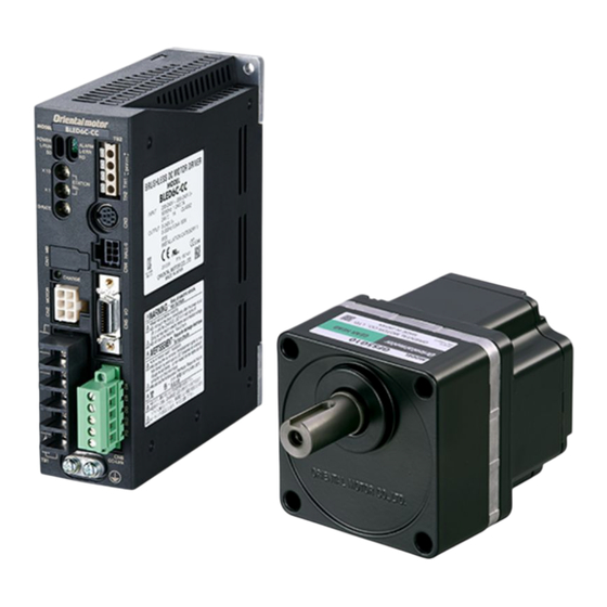
Brushless Motor and Driver Package
BLE
Series CC-Link
Installation/Connection
OPERATING MANUAL
Thank you for purchasing an Oriental Motor product.
This Operating Manual describes product handling procedures and safety precautions.
• Please read it thoroughly to ensure safe operation.
• Always keep the manual where it is readily available.
Table of contents
1
Introduction ........................................................2
2
Safety precautions ............................................3
3
Precautions for use ...........................................5
4
Preparation ..........................................................7
4.1
Checking the product ......................................... 7
4.2
Combination tables .............................................. 8
4.3
Names and functions of parts .......................... 8
5
Installation ........................................................ 10
5.1
Installation location............................................10
5.2
parallel shaft gearhead ....................................10
5.3
hollow shaft flat gearhead .............................12
5.4
Installing the round shaft type .......................15
5.5
parallel gearhead or round shaft type .......16
5.6
hollow shaft flat gearhead .............................18
5.7
Installing the driver ............................................19
5.8
Installing the regeneration unit .....................20
5.9
Conformity to the EMC .....................................21
6
Connection ....................................................... 23
6.1
Connecting the power supply ........................23
6.2
Grounding .............................................................24
6.3
Connecting the motor.......................................25
6.4
input .......................................................................26
6.5
Connecting the regeneration unit ................26
6.6
Connecting the I/O signals ..............................27
6.7
Connecting the communication cable .......30
6.8
cable .......................................................................30
6.9
Connecting example .........................................31
7
Maintenance and inspection ..................... 33
7.1
Inspection ..............................................................33
7.2
Warranty .................................................................33
7.3
Disposal ..................................................................33
8
Specifications ................................................... 34
8.1
Specifications .......................................................34
8.2
General specifications .......................................35
8.3
Dimension .............................................................35
9
Regulations and standards ......................... 36
9.1
UL Standards, CSA Standards .........................36
9.2
CE Marking ............................................................36
9.3
RoHS Directive .....................................................38
9.4
Republic of Korea, Radio Waves Act .............38
HM-5280-2
Advertisement
Table of Contents

Related Manuals for Oriental motor CC-Link BLE Series


Summary of Contents for Oriental motor CC-Link BLE Series
-
Page 1: Table Of Contents
Series CC-Link Installation/Connection OPERATING MANUAL Thank you for purchasing an Oriental Motor product. This Operating Manual describes product handling procedures and safety precautions. • Please read it thoroughly to ensure safe operation. • Always keep the manual where it is readily available. -
Page 2: Introduction
The product described in this manual has been designed and manufactured to be incorporated in general industrial equipment. Do not use for any other purpose. Oriental Motor Co., Ltd. is not responsible for any damage caused through failure to observe this warning. -
Page 3: Safety Precautions
Safety precautions 2 Safety precautions The precautions described below are intended to prevent danger or injury to the user and other personnel through safe, correct use of the product. Please read and understand these precautions thoroughly before using the product. Handling the product without observing the instructions that accompany a "WARNING"... - Page 4 • Do not disassemble or modify the motor (gearhead) and driver. Doing so may result in electric shock, injury or equipment damage. Should you require inspection or repair of internal parts, please contact the Oriental Motor branch or sales office from which you purchased the product.
-
Page 5: Precautions For Use
Precautions for use 3 Precautions for use This chapter explains the restrictions and other items you should take heed of when using the BLE Series. „ Connect protective devices to the power line Connect a circuit breaker or earth leakage breaker to the driver’s power line to protect the primary circuit. If an earth leakage breaker is to be installed, use one incorporating high-frequency noise elimination measures. - Page 6 Precautions for use „ Noise elimination measures Provide the following noise elimination measures to prevent a motor or driver malfunction caused by external noise. z Wiring the motor Use connection cable (supplied or sold separately) when extending the wiring distance between the motor and driver. z Wiring the I/O signal cable •...
-
Page 7: Preparation
Preparation 4 Preparation This chapter explains what you must do before using the BLE Series, as well as the name and function of each part of the unit. 4.1 Checking the product Verify that the items listed below are included. Report any missing or damaged items to the branch or sales office from which you purchased the product. -
Page 8: Combination Tables
Preparation 4.2 Combination tables • in the model names indicates a number representing the gear ratio. • „ in the model names indicates a number representing the length of a connection cable. (This number is not described in the model name when the connection cable is not included in the product.) „... - Page 9 Preparation „ Driver Mounting hole Control power supply CC-Link station number input terminal setting switches Regeneration resistor thermal input terminal CC-Link transmission baud-rate setting switch Communication connector Motor signal connector CHARGE LED I/O signal connector Motor connector Regeneration resistor terminal CC-Link connector Power supply input terminal...
-
Page 10: Installation
Installation 5 Installation 5.1 Installation location The motor and driver are designed and manufactured for use as internal components of equipment. Install the motor and driver in a well-ventilated place where they can be inspected easily and the following conditions are satisfied: •... - Page 11 Installation 2. Install the supplied hexagonal socket head screw in the four mounting holes you just opened and tighten the nuts until no gaps remain between the motor and mounting plate. Model Nominal thread size Tightening torque Hexagonal socket head screw BLE23 1.8 N·m (15.9 lb-in) BLE46...
-
Page 12: Installing The Combination Type Hollow Shaft Flat Gearhead
Installation 5.3 Installing the combination type hollow shaft flat gearhead A combination type hollow shaft flat gearhead can be installed by using either its front or rear side as the mounting surface. Install the supplied hexagonal socket head screw in the four mounting holes you opened and tighten the nuts until no gaps remain between the motor and mounting plate. - Page 13 Installation z Installing the safety cover After installing a load, attach the included safety cover. The safety cover can be attached to either face. Tightening torque: 0.45 N·m (3.9 lb-in) Mounting screw for safety cover (M3) Safety cover z Mounting hole dimension [unit: mm (in.)] Model ØA ØBH8...
- Page 14 Installation „ Installing/removing the hollow shaft flat gearhead The gearhead can be removed and the motor cable position changed to one of three 90° directions. Note that the motor cable cannot be positioned in the direction where the cable faces the gearhead output shaft. 1.
-
Page 15: Installing The Round Shaft Type
Installation 5.4 Installing the round shaft type Install the motor to a mounting plate of the following size or larger, so that the motor case temperature will not exceed 90 °C (194 °F). Model Size of radiation plate [mm (in.)] Thickness [mm (in.)] Material BLE23... -
Page 16: Installing A Load On The Combination Type Parallel Gearhead Or Round Shaft Type
Installation 5.5 Installing a load on the combination type parallel gearhead or round shaft type When installing a load on the motor (gearhead), align the center of the motor output shaft (gearhead output shaft) with the center of the load shaft. •... - Page 17 Installation „ Permissible radial load and permissible axial load Make sure the radial load and axial load received by the gearhead output shaft will not exceed the allowable values shown in the table below. If the radial load or axial load exceeds the specified allowable value, repeated load applications may cause Note the bearing or output shaft of the gearhead to undergo a fatigue failure.
-
Page 18: Installing A Load On The Combination Type Hollow Shaft Flat Gearhead
Installation 5.6 Installing a load on the combination type hollow shaft flat gearhead If the motor is subject to a strong impact upon instantaneous stop or receives a large radial load, use a stepped load shaft. Apply grease (molybdenum disulfide grease, etc.) on the surface of the load shaft and inner walls of the Note hollow output shaft to prevent seizure. -
Page 19: Installing The Driver
Installation „ Permissible radial load and permissible axial load Make sure the radial load and axial load received by the gearhead output shaft will not exceed the allowable values shown in the table below. If the radial load or axial load exceeds the specified allowable value, repeated load applications may cause Note the bearing or output shaft of the gearhead to undergo fatigue failure. -
Page 20: Installing The Regeneration Unit
Installation z Mounting to DIN rail Use a separately sold DIN rail mounting plate (model number: PADP03) and attach it to a 35 mm (1.38 in.) wide DIN rail. After installation, fix the both sides of the driver with the end plate (not supplied). DIN rail mounting plate DIN rail... -
Page 21: Conformity To The Emc
The use of the following installation and wiring methods will enable the motor and driver to be compliant with the EMC. Oriental Motor conducts EMC testing on its motors and driver in accordance with "Example of motor and driver installation and wiring" on p.22. - Page 22 • Use connection cable (supplied or sold separately) when extending the wiring distance between the motor and driver. The EMC measures are conducted using the Oriental Motor connection cable. „ Precautions about static electricity Static electricity may cause the driver to malfunction or become damaged.
-
Page 23: Connection
Connection 6 Connection 6.1 Connecting the power supply Connect the power cable to the Power supply input terminal (TB1) on the driver. The connection method varies depending on the input power supply voltage. • Confirm the power supply voltage and the driver’s rated voltage. To protect the primary circuit, connect a Note protective device to the driver’s power line. -
Page 24: Grounding
Connection „ Circuit breaker Be sure to connect a circuit breaker er to the power line of the driver to protect the primary circuit. Rated current of protective device Model Rated current BLE23A, BLE23C, BLE46C, BLE512C *1 BLE46A, BLE512A, BLE512C *2 10 A *1 Three phase 200-240 V input *2 Single-phase 200-240 V input... -
Page 25: Connecting The Motor
Connection 6.3 Connecting the motor Insert the motor cable into the motor connector (CN2) and motor signal connector (CN4) of the driver. To expand connection between the motor and driver, use the connection cable (supplied or sold separately). Connection can be extended to a maximum of 20.4 m (66.9 ft.). -
Page 26: Connecting The Control Power Supply Input And Regeneration Resistor Thermal Input
Connection 6.4 Connecting the control power supply input and regeneration resistor thermal input Connect the control power supply input and regeneration resistor thermal input to TB2. Connect the lead wire to the connector while checking the pin numbers in below. Display Description Display... -
Page 27: Connecting The I/O Signals
Connection „ Regeneration unit specifications Model RGB100 Continuous regenerative power 100 W Resistance 150 Ω Operation: Opens at 150±7 °C (302±45 °F) Operating temperature of thermostat Reset: Closes at 145±12 °C (293±54 °F) (normally closed) Electrical rating of thermostat 120 VAC 4 A, 30 VDC 4 A (minimum current: 5 mA) * Install the regeneration unit in a location where heat dissipation capacity equivalent to a level achieved with a heat sink [made of aluminum, 350×350×3 mm (13.78×13.78×0.12 in.)] is ensured. - Page 28 Connection „ Assembling the connector Cable clamp Screw (M2.6) Screw (M2) Tightening torque: I/O signal cable 0.294 N·m (41 oz-in) or less Connector Case Place the spring washer outside the case. Screw (M2.6) Align the at washer in the depression in the case. „...
- Page 29 Connection „ Connecting to a current source output circuit Programmable controller Driver 24 VDC 4.7 k: 1 k: 4.7 k: 1 k: 4.7 k: 1 k: 4.7 k: 1 k: 30 VDC or less →40 mA or less →40 mA or less Use output signals at 30 VDC or less.
-
Page 30: Connecting The Communication Cable
Connection 6.7 Connecting the communication cable Connect to the communication connector (CN3) on the driver the OPX-2A cable or the support software communication cable. MEXE02 is supported from the software version of 1.20 or later. OPX-2A cable or support software communication cable 6.8 Connecting the CC-Link communication cable Connect the CC-Link connection cable using the supplied CC-Link connector (5-pin). -
Page 31: Connecting Example
Connection 6.9 Connecting example The connection example described below assumes that the motor is operated using a single-phase 100-120 V power supply. „ Sink logic Main circuit Circuit breaker POWER Power supply connection Motor cable Grounding the driver Motor connection Regeneration connector unit connection... - Page 32 Connection „ Source logic Main circuit Circuit breaker POWER Power supply connection Motor cable Grounding the driver Motor connection Regeneration connector unit connection Motor R: 150 : Control circuit N.C. Grounding 150 °C Motor signal the motor (302 °F) connector Control power supply 24V+ connection...
-
Page 33: Maintenance And Inspection
• The power elements and smoothing capacitors in the driver are not generating an abnormal smell or having abnormalities. 7.2 Warranty Check on the Oriental Motor Website for the product warranty. 7.3 Disposal Dispose the product correctly in accordance with laws and regulations, or instructions of local governments. -
Page 34: Specifications
Specifications 8 Specifications 8.1 Specifications The value in a state where the gearhead is not combined is described in each specification for the "rated torque," "maximum instantaneous torque," "rated rotation speed" and "speed control range." • in the model names indicates a number representing the gear ratio. •... -
Page 35: General Specifications
Specifications 8.2 General specifications Motor Driver Ambient 0 to +50 °C [+32 to +122 °F] (non-freezing) temperature Ambient 85% or less (non-condensing) humidity Altitude Up to 1000 m (3300 ft.) above sea level No corrosive gas, dust, water or oil. Surrounding Operating Cannot be used in radioactive materials, magnetic field, vacuum or other special... -
Page 36: Regulations And Standards
Regulations and standards 9 Regulations and standards 9.1 UL Standards, CSA Standards This product is recognized by UL under the UL and CSA Standards. 9.2 CE Marking This product is affixed with the marks under the following directives. „ Low Voltage Directive Installation conditions Motor Driver... - Page 37 Regulations and standards z The driver is not provided with the ground fault protection. Wire the product in accordance with "Wiring example having considered ground fault protection." Also observe the followings. • Earth leakage breaker: Rated sensitivity current 30 mA •...
-
Page 38: Rohs Directive
Regulations and standards • TT power distribution systems Earth leakage breaker Driver Fault loop Grounding Grounding Three-phase 200-240 V • TN power distribution systems Earth leakage breaker Driver Fault loop Grounding • TT power distribution systems Earth leakage breaker Driver Grounding Grounding Fault loop... - Page 39 Regulations and standards...
- Page 40 • Unauthorized reproduction or copying of all or part of this manual is prohibited. If a new copy is required to replace an original manual that has been damaged or lost, please contact your nearest Oriental Motor branch or sales office.
Need help?
Do you have a question about the CC-Link BLE Series and is the answer not in the manual?
Questions and answers