Oriental motor BLE2 Series Operating Instructions Manual
Brushless motor
Hide thumbs
Also See for BLE2 Series:
- Operating manual (52 pages) ,
- Quick start manual (2 pages) ,
- Operating manual (8 pages)
Table of Contents
Advertisement
Quick Links
OPERATING MANUAL
Brushless Motor
BLE2 Series
Thank you for purchasing an Oriental Motor product.
This Operating Manual describes product handling
procedures and safety precautions.
● Please read the manual thoroughly to ensure safe operation.
● Always keep the manual where it is readily available.
● Only qualified personnel of electrical and mechanical engineering
should work with the product.
● The product described in this manual has been designed
and manufactured to be incorporated in general industrial
equipment. Do not use for any other purpose. Oriental Motor
Co., Ltd. is not responsible for any compensation for damage
caused through failure to observe this warning.
Safety precautions
Be sure to read before using the
product. Use the product correctly
after thoroughly reading this
section.
Preparation
Precautions for use .....................................6
Related operating manuals .....................8
System configuration ................................9
Checking the product .............................10
Installing.......................................................13
Connecting..................................................16
How to use
Operating .....................................................36
Convenient functions ..............................47
Operation panel ........................................48
Parameters ..................................................56
MEXE02 ......................................................65
Help
Maintenance and inspection ................69
Troubleshooting ........................................70
Alarm .............................................................72
Information .................................................74
Appendix
Specifications .............................................76
Regulations and standards ....................80
Cable and peripheral equipment ........85
HP-5105-8
Advertisement
Table of Contents

Subscribe to Our Youtube Channel
Related Manuals for Oriental motor BLE2 Series


Summary of Contents for Oriental motor BLE2 Series
-
Page 1: Table Of Contents
● The product described in this manual has been designed and manufactured to be incorporated in general industrial equipment. Do not use for any other purpose. Oriental Motor Co., Ltd. is not responsible for any compensation for damage caused through failure to observe this warning. - Page 2 Table of contents Be sure to read before using the product. Safety precautions..4 Use the product correctly after thoroughly reading this section. Preparation How to use Precautions for use ....6 Operating ......36 1. Operating using the operation panel ....36 Related operating manuals ..8 2.
- Page 3 Help Parameters ......56 Maintenance and inspection 69 1. Parameter list ..............56 1. Inspection ..............69 2. Timing for parameter to update ......58 2. Warranty ................. 69 3. Explanation of parameters ........58 3. Disposal ................69 3-1 Base settings parameters ......... 58 Troubleshooting ....70 3-2 Speed/torque limiting adjustment parameters ............
-
Page 4: Safety Precautions
Safety precautions The precautions described below are intended to ensure the safe and correct use of the product, and to prevent the user and other personnel from exposure to the risk of injury. Use the product only after carefully reading and fully understanding these instructions. WARNING Handling the product without observing the instructions that accompany a "WARNING"... -
Page 5: Warning Information
Maintenance and inspection Do not touch the motor or driver when conducting the insulation resistance measurement or dielectric strength test. Accidental contact may result in Do not touch the connection terminals on the driver immediately (until the CHARGE LED turns electric shock. -
Page 6: Precautions For Use
Precautions for use This chapter covers restrictions and requirements the user should consider when using the product. Be sure to match the motor output power with the driver output power. Wirings z Connect protective devices to the power line Connect a circuit breaker or earth leakage breaker to the driver power line to protect the primary circuit. If an earth leakage breaker is installed, use one incorporating high-frequency noise elimination measures. -
Page 7: Saving The Data
Insulation resistance measurement and dielectric strength test Do not conduct the insulation resistance measurement or dielectric strength test with the motor and driver connected. Conducting the insulation resistance measurement or dielectric strength test with the motor and driver connected may result in damage to the product. -
Page 8: Related Operating Manuals
Related operating manuals Operating manuals are not included with the product. Download from Oriental Motor Website Download Page or contact your nearest Oriental Motor sales office. Operating manual name Driver BLE2 Series OPERATING MANUAL (this document) BLM Motor OPERATING MANUAL... -
Page 9: System Configuration
System configuration The system configuration of the BLE2 Series is shown below. The figure below shows the driver for the electromagnetic brake motor. x Setting of operation data and parameters Motor (sold separately) PC in which the support software Driver... -
Page 10: Checking The Product
Checking the product This chapter explains the items you should check, as well as the name and function of each part. 1. Package contents Verify that the items listed below are included. Report any missing or damaged items to the branch or sales office from which you purchased the product. ... -
Page 11: Products Possible To Combine
4. Products possible to combine Products with which the drivers can be combined are listed below. Verify the driver model and the motor model against the model name described on the package label. Motor model columns in the table below describes part of the motor model name. Refer to the operating manual of the motor for details about the motor models. -
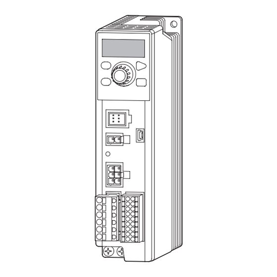
Page 12: Names And Functions Of Parts
5. Names and functions of parts Protective film Use after removing the protective film. Display Operation panel Operation keys Setting dial ALARM LED LOCAL LED Sensor connector (CN4) USB communication connector Electromagnetic brake connector (CN3) ∗ CHARGE LED Motor connector (CN2) I/O signals connector (CN5) Regeneration resistor terminal (CN1) -
Page 13: Installing
Installing This chapter explains the installation location and installation method. 1. Installation location Install the product in a well-ventilated location that provides easy access for inspection. The location must also satisfy the following conditions: • Inside an enclosure that is installed indoors (provide vent holes) •... -
Page 14: Installation Method
2. Installation method The driver is designed so that heat is dissipated via air convection and conduction through the enclosure. When installing the driver, provide clearances of at least 25 mm (0.98 in.) in the horizontal and vertical directions between the driver and enclosure or other equipment within the enclosure. - Page 15 „ When a driver is installed to a DIN rail Operating ambient temperature: 0 to +40°C (+32 to +104 °F) Use the DIN rail mounting plate MADP02 (sold separately), and install it to a 35 mm (1.38 in.) wide DIN rail. After installing to the DIN rail, secure the both sides of the DIN rail driver with end plates that the customer provides.
-
Page 16: Connecting
Connecting This chapter explains how to connect the motor, I/O signals and power supply to the driver, as well as grounding method using the driver for electromagnetic brake motor. For protection against electric shock, do not turn on the power supply until the wiring is completed. Motor Driver Input signal ⇒... -
Page 17: Connecting The Motor And Driver
2. Connecting the motor and driver Connect the motor and driver using the connection cable (sold separately). The connection cables are provided up to 20 m (65.6 ft.). For about the connection methods of the motor and connection cable, refer to the operating manual of the motor. Insert into Connection cable the driver... -
Page 18: Grounding
3. Grounding Ground using the Protective Earth Terminals of the motor and driver, as well as the ground terminal of the connection cable. Be sure to ground the product. Failure to do so may result in electric shock or damage to the product. Note Static electricity may cause damage to the product if the Protective Earth Terminals are not grounded. -
Page 19: Connecting The I/O Signals (Cn5)
4. Connecting the I/O signals (CN5) Connect the input signals and output signals to CN5. „ Connection method Applicable lead wire 10 mm Screwdriver (0.39 in.) • Lead wire size: Stranded wire AWG24 to 18 (0.2 to 0.75 mm • Conductive material: Use only copper wires. Lead wire Applicable crimp terminal Manufacturer: PHOENIX CONTACT GmbH &... - Page 20 „ Input signals circuit All input signals of the driver are photocoupler inputs. When an external power supply is used: 20.4 to 28.8 VDC, 100 mA or more +5 V Pin No. 680 Ω 6.6 kΩ 1 kΩ 2 to 8 Photocoupler z Changing the logic level setting of input signals The logic level setting for input terminals IN0 to IN6 can be changed using the MEXE02 or operation panel.
-
Page 21: Connecting External Analog Setting Devices
5. Connecting external analog setting devices Using an external potentiometer (sold separately) or external DC voltage, the analog setting for the rotation speed or torque limiting value can be performed. Refer to p.38, 41 and p.59 for the setting method. „... -
Page 22: Connecting The Usb Cable
6. Connecting the USB cable Connect the USB cable to the USB communication connector when using the MEXE02. Specifications of USB cable USB cable Specifications USB2.0 (full speed) Length: 3 m (9.8 ft.) or less Cable Shape: A to mini-B USB communication connector •... -
Page 23: Connecting The Regeneration Resistor
7. Connecting the regeneration resistor If continuous regeneration operation such as gravitational operation in vertical drive is performed or an inertia load is operated with the round shaft type motor of 300 W or higher, use the regeneration resistor RGB100 (sold separately). Also, if the stopping time gets longer when starting and stopping operations of a large inertia load are repeated frequently, use the regeneration resistor. -
Page 24: Connection Diagram
8. Connection diagram „ Sink logic z When using the internal power supply This is a connection example when the electromagnetic brake motor and the driver of single-phase 100-120 VAC are used, the rotation speed is externally set, and the internal power supply is used for input signals. I/O signals in brackets [ ] are set at the time of shipment. - Page 25 z When using an external power supply This is a connection example when the electromagnetic brake motor and the driver of single-phase 100-120 VAC are used, and the motor is operated by setting the rotation speed externally. I/O signals in brackets [ ] are set at the time of shipment. Refer to p.65 for the assignment of I/O signals.
- Page 26 „ Source logic When using an external power supply This is a connection example when the electromagnetic brake motor and the driver of single-phase 100-120 VAC are used, and the motor is operated by setting the rotation speed externally. I/O signals in brackets [ ] are set at the time of shipment. Refer to p.65 for the assignment of I/O signals.
-
Page 27: X84; Connection Example For I/O Signals And Programmable Controller
„ Connection example for I/O signals and programmable controller z Sink logic Programmable controller Driver 24 VDC IN-COM0 6.6 kΩ 1 kΩ 6.6 kΩ 1 kΩ 6.6 kΩ 1 kΩ 6.6 kΩ 1 kΩ 6.6 kΩ 1 kΩ 6.6 kΩ 1 kΩ... - Page 28 z Source logic Programmable controller Driver 24 VDC IN-COM0 6.6 kΩ 1 kΩ 6.6 kΩ 1 kΩ 6.6 kΩ 1 kΩ 6.6 kΩ 1 kΩ 6.6 kΩ 1 kΩ 6.6 kΩ 1 kΩ 6.6 kΩ 1 kΩ IN-COM1 Do not connect anything. 4.5 to 30 VDC 100 mA or less→...
-
Page 29: I/O Signals
9. I/O signals This section explains about input signals and output signals. I/O signals list „ Input signals Reference Signal name Function Description page This is a signal to operate the motor. When either the FWD input or the REV input is turned ON, the motor rotates. The motor stops when the signal is turned OFF. -
Page 30: Timing Chart When Power Is Input
Timing chart when power is input This timing chart describes the timing of input signals and output signals when the power supply is turned on. Main power supply 0.5 s or less Output signal Signal is output 0.5 s or more Input signal Input enabled Description of input signals... - Page 31 „ 3-Wire mode z START/STOP input, RUN/BRAKE input The motor rotates when both the START/STOP input and the RUN/BRAKE input are turned ON. When the START/STOP input is turned OFF while the motor is rotating, the motor decelerates to a stop according to the deceleration time of the operation data number.
- Page 32 „ M0 to M3 inputs A desired operation data number can be selected by a combination of ON-OFF status of the M0 to M3 inputs. The M0 and M1 inputs are assigned at the time of shipment. If the M2 and M3 inputs are assigned, the operation of 16 speeds can be performed.
- Page 33 „ Other inputs z MB-FREE input (Available for only drivers for electromagnetic brake motor) This input signal can be used to operate whether the electromagnetic brake holds or releases while the motor stops. When this input is turned ON at motor standstill, the electromagnetic brake is released to bring the motor shaft in a free-run state.
-
Page 34: Description Of Output Signals
Description of output signals „ SPEED-OUT output 30 pulses are output while the motor output shaft makes one revolution in synchronization with the motor operation. The pulse width of output pulse signals is 0.2 ms. The motor rotation speed can be calculated using the SPEED-OUT output. Frequency of the SPEED-OUT (Hz) = Frequency of the SPEED-OUT Rotation speed (r/min) =... - Page 35 „ VA output This signal is turned ON when the detection speed reaches "plus or minus range of VA detection width against the setting speed." The width to turn the VA output ON can be set using the "VA detection width" parameter (ID: 1817). Related parameters Factory Parameter name...
-
Page 36: Operating
Operating There are two methods to operate the motor. Operating using the operation panel Operating using external signals The motor can be operated using the operation panel of the driver. The motor can be operated using external signals or the MEXE02. Driver Driver Motor... -
Page 37: Operating Using External Signals
2. Operating using external signals Overview Driver The motor can be operated by setting up to 16 operation data and selecting the operation data number externally. Motor Operation Factory Reference Item Setting range Programmable data No. setting page controller, etc. Rotation speed 50 to 4000 r/min Torque limiting... - Page 38 2-3-2 When setting with the external potentiometer or external DC voltage When the rotation speed is set using the external potentiometer or external DC voltage, the setting of the “Speed, torque limiting command selection" parameter is required to change. Check the connection 0 to 20 External potentiometer Pin No.13...
-
Page 39: Operation/Standstill Using External Signals
Operation/standstill using external signals To switch between operation and stop of the motor in the 2-wire mode, the FWD input and the REV input are used. This section explains as an example when the “2-Wire mode 1" is selected with the "Operation input mode selection" parameter. Refer to p.64 for the operation input mode. -
Page 40: Gain Adjustment And Offset Adjustment For Rotation Speed
Gain adjustment and offset adjustment for rotation speed If the gain or offset is adjusted when the rotation speed is set using the external potentiometer or external DC voltage, the slope of the speed command can be changed and the speed can finely be adjusted. Note The rotation speed corresponding to the voltage value varies depending on the product. -
Page 41: Setting Of Torque Limiting
3. Setting of torque limiting The maximum output torque of the motor can be limited. Set when suppressing the motor output torque for safe uses or limiting according to a load. [Setting range: 0 to 300%] If the time to lock the motor shaft exceeds five seconds, use the torque limiting value at 50% or less. „... -
Page 42: Gain Adjustment And Offset Adjustment For Torque Limiting Value
Gain adjustment and offset adjustment for torque limiting value If the gain or offset is adjusted when the torque limiting value is set using the external potentiometer or external DC voltage, the slope or lower limit of the command can be set. Note The torque limiting value corresponding to the voltage value varies depending on the product. -
Page 43: Setting Of Acceleration/Deceleration Time
4. Setting of acceleration/deceleration time The acceleration time and deceleration time can be set to prevent a load from receiving a shock upon starting or stopping. Setting range: 0.0 to 15.0 seconds (factory setting: 0.5 seconds) Acceleration time refers to the time needed for the motor to reach the 3000 r/min rated rotation speed (3000 r/min) from the standstill status. -
Page 44: Setting Of Rotation Direction
5. Setting of rotation direction „ Rotation direction of the motor output shaft The rotation direction of the motor output shaft represents the direction when viewed from the motor output shaft side. The rotation direction can be changed with the parameter. (REV input signal) (FWD input signal) Related parameters... - Page 45 „ Data setting method (Example: Rotation speed) Operation panel Turn on the AC power supply MODE Rotation speed : 0 r/min Data mode Setting dial Press twice Data number Data No.0 : Press selection screen The desired operation data number can be selected from the operation data No.0 to No.15 (16 data) by turning The desired item can be selected by turning...
-
Page 46: Adjusting The Rotation Speed Of Two Or More Motors By A Single Setting Device (Multi-Motor Control)
7. Adjusting the rotation speed of two or more motors by a single setting device (multi-motor control) Multiple motors can be operated at the same speed using a single variable resistor or external DC voltage. • Change the "Speed, torque limiting command selection" parameter (ID: 1820) to "1" or "2" of the analog setting when operating in this method. -
Page 47: Convenient Functions
Convenient functions Display Displaying the rotation speed of the gearhead output shaft p.58 Displaying the transfer speed of the conveyor drive p.58 Displaying the speed increased by an external mechanism p.58 Displaying the motor output torque p.50 Displaying the operation data number presently selected p.50 Changing the display at power ON p.65... -
Page 48: Operation Panel
Operation panel This chapter explains how to set data and how to operate a motor using the operation panel on the driver. 1. Operation panel This chapter explains the name and function of each part of the operation panel as well as function modes. Names and functions of parts Display MODE key... -
Page 49: Function Mode Types
Function mode types There are four operation modes in this product. On the top screen of each mode, pressing the key or turning the setting dial will switch the operation mode. The top screens for each mode are shown below. Monitor mode (p.50) This is a mode to be displayed when turning on the power. -
Page 50: Operation Transitions
2. Operation transitions Items that can be monitored Operation panel How to read the marks Top screen of monitor mode Turn Turn Press clockwise counterclockwise ↓ ↓ ↓ Increase Decrease Press Setting dial In the lower level except the top screen, When the power is turned on, "rotation speed"... - Page 51 „ Rotation speed The motor rotation speed can be checked. The rotation speed can be displayed as the rotation speed of the gearhead output shaft. To do this, set with the "Speed reduction ratio" parameter (ID: 2033) and "Speed reduction ratio digit setting" parameter (ID: 2038). It is also possible to increase the rotation speed and display the increased speed.
-
Page 52: Setting Of Operation Data
Setting of operation data Operation panel How to read the marks Top screen of data mode Turn Turn Press clockwise counterclockwise ↓ ↓ ↓ Press Increase Decrease Setting dial In the lower level except the top screen, press to return to the previous level. Press Press Data No.0... -
Page 53: Setting Of Parameters
Setting of parameters Operation panel How to read the marks Top screen of parameter mode Turn Turn Press clockwise counterclockwise ↓ ↓ ↓ Increase Decrease Setting dial Press In the lower level except the top screen, press to return to the previous level. Press Press Parameter ID... -
Page 54: Test Mode
Test mode Operation panel How to read the marks Top screen of test mode Turn Turn Press clockwise counterclockwise ↓ ↓ ↓ Press Increase Decrease Setting dial In the lower level except the top screen, press to return to the previous level. Press Press I/O test... -
Page 55: Edit Lock Function
„ I/O test With the I/O test, the ON-OFF status of each input signal can be checked, and the ON-OFF status of each output signal can be switched. The ALARM LED on the driver blinks in orange when the screen is moved to the I/O test. During the I/O test screen, the I/O terminals of CN5 are disabled, and the motor does not rotate even if the operation input signal is turned ON. -
Page 56: Parameters
Parameters 1. Parameter list Factory Reference Parameter name Setting range Update *1 setting page − Driver user name Up to 16 characters − 0: Digital setting 1: Analog setting for the speed No.1, and digital setting for others 2: Analog setting for speed, 1820 Speed, torque limiting command selection and digital setting for torque limiting... - Page 57 Factory Reference Parameter name Setting range Update *1 setting page 1964 INFO action (Operation prohibited information (INFO-DRV)) *3 1972 INFO action (Tripmeter information (INFO-TRIP)) *3 1973 INFO action (Odometer information (INFO-ODO)) *3 INFO action (Main power supply time information 1978 (INFO-PTIME)) *3 INFO action (Main power supply count information 0: INFO action is not applied...
-
Page 58: Timing For Parameter To Update
2. Timing for parameter to update Parameters can be set using the operation panel or MEXE02. When parameters are written to the driver, they are saved in the non-volatile memory. The parameters saved in the non-volatile memory are stored even after the power supply is turned off. When a parameter is changed, the timing to update the new value varies depending on the parameter. - Page 59 „ Setting method of the rotation speed and torque limiting value The setting method can be selected using the "Speed, torque limiting command selection" parameter. Refer to the table below for four types of parameter setting methods. z "Speed, torque limiting command selection" parameter (ID: 1820) Setting value: 0 Setting value: 1 Setting value: 2...
-
Page 60: Speed/Torque Limiting Adjustment Parameters
„ Display when setting the speed reduction ratio The position of the decimal point displayed on the rotation speed monitor varies as shown in the table below depending on the set speed reduction ratio or conveyor speed reduction ratio. Setting of speed reduction ratio, calculated Displayed decimal point conveyor speed reduction ratio position... -
Page 61: Alarm/Information Setting Parameters
Alarm/information setting parameters A: Update immediately, C: Update after executing configuration or turning on the power again Factory Parameter name Description Setting range Update setting Sets the detection time of the overload alarm. 384 Overload alarm detection time 0.1 to 40.0 [s] 30.0 200 W or lower: At a time of about 180% load 300 W or higher: At a time of about 150% load... -
Page 62: Operation Parameters
„ Changing the overload alarm detection time You can change the time till the overload alarm is detected after the motor output torque exceeded the overload detection level. The time when the overload alarm is generated varies according to the load factor of the motor. Overload alarm detection time The time set in the "Overload alarm detection time"... - Page 63 „ Holding a load at motor standstill Although the electromagnetic brake motor can hold a load by the electromagnetic brake when the motor stops, even if a motor without an electromagnetic brake is used, a certain degree of holding force can be generated at motor standstill by the load holding function.
-
Page 64: I/O Action Parameters
I/O action parameters A: Update immediately, C: Update after executing configuration or turning on the power again Factory Parameter name Description Setting range Update setting 0: 2-Wire mode 1 Selects whether the operation input signal is used in the 2-wire mode or 1: 3-Wire mode 1 Operation input mode the 3-wire mode. -
Page 65: Mexe02
MEXE02 I/O function selection parameters C: Update after executing configuration or turning on the power again Factory Parameter name Description Setting range Update setting 2112 IN0 input function selection 2113 IN1 input function selection 2114 IN2 input function selection Assigns the input signals to the input Refer to the "Input function selection"... -
Page 66: Starting Mexe02
Select the product. Series: BLE2 Prodcut: BLE2 2. Monitor „ Unit information monitor The device information of the BLE2 Series can be monitored. z How to view the unit information monitor window Item Description Driver user name Monitors the name set in the "Driver user name" parameter. - Page 67 „ D-I/O monitor The ON-OFF status of the I/O signals of the BLE2 Series and the setting value of the external analog setting device can be monitored. D-I/O represents direct I/O. „ I/O test I/O signals of D-I/O can be tested. Forcible output of output signals in addition to monitors of input signals and external DC voltage can be executed.
-
Page 68: Teaching, Remote Operation
„ Waveform monitor The motor rotation speed or the status of I/O signals can be checked in a waveform format. Refer to the operating manual of the MEXE02 for the procedures to operate the applicable products using the MEXE02. z CH1 to CH4 (analog CH) The rotation speed or the detected torque (actual torque), etc. -
Page 69: Maintenance And Inspection
It is recommended that periodic inspections for the items listed below are conducted after each operation of the motor. If an abnormal condition is noted, discontinue any use and contact your nearest Oriental Motor sales office. • Do not conduct the insulation resistance measurement or dielectric strength test with the motor and driver Note connected. -
Page 70: Troubleshooting
When the motor cannot be operated properly, refer to the contents provided in this chapter and take appropriate action. If the problem persists, contact your nearest Oriental Motor sales office. • Check the alarm contents when an alarm is generated. - Page 71 ● The motor and gearhead output shaft and a load shaft are out of alignment. ▷ Check the installation status of the motor (gearhead) output shaft and load shaft. The motor movement is not ● The product is affected by electrical noise. ▷...
-
Page 72: Alarm
Alarm This driver has the alarm function to protect from temperature rise, poor connection, error in operation, and others. If an alarm is generated, the ALARM-OUT output is turned OFF, and the motor stops. At the same time, the alarm code is displayed on the operation panel, and the ALARM LED blinks in red. Configuration cannot be executed while an alarm is generated. - Page 73 Reset by the Alarm Cause Remedial action ALARM-RESET ● Reconsider the ambient temperature. ● The temperature inside the driver exceeded the ● Reconsider the ventilation condition in the Possible detection temperature of the alarm. enclosure. Main circuit overheat ● Check the power supply voltage. ●...
-
Page 74: Information
Information The driver is equipped with a function to generate information output before an alarm is generated. This function can be utilized for periodic maintenance of equipment by setting a suitable value in the parameter of each information. Contents of information can be checked using the MEXE02 or the monitor mode of the operation panel. z INFO output If information is generated, the INFO output is turned ON. - Page 75 Information bit Information Cause Condition to reset and clear output signal ● The operation input signal is being ON when the test mode has switched to other mode. ● The operation input signal is being ON when I/O test of the MEXE02 or teaching/ remote operation has completed.
-
Page 76: Specifications
Specifications 1. Specifications Values in the rated torque, peak torque, rated rotation speed, and speed control range represent those in a state where the gearhead is not combined. Motor model columns in the table below describes part of the motor model name. Refer to the operating manual of the motor for details about the motor models. -
Page 77: General Specifications
z 300 W and 400 W BLM6300SHP BLM6400SHP Motor BLM5300HP BLM5400HP Model BLM7300HW BLM7400HW BLE2D300-C BLE2D400-C BLE2D400-S Driver Rated output power (Continuous) 300 W 400 W Single-phase 200-240 VAC Rated voltage Single-phase 200-240 VAC Three-phase 200-240 VAC Three-phase 200-240 VAC Permissible voltage range –15 to +10% Rated frequency... -
Page 78: Dimensions
3. Dimensions z 30 W, 60 W, 120 W, 200 W (BLE2D200-C, BLE2D200-CM 300 W, 400 W (BLE2D400-S Mass: 0.8 kg (1.76 lb.) [Unit: mm (in.)] ( 1.18 ) 5 ( 0.20 ) 4.5 ( 0.177 ) Thru (0.71) 11 ( 0.43 ) 40 ( 1.57 ) 9 ( 0.35 ) R2.25 ( 0.089 ) -
Page 79: Pin Assignment
4. Pin assignment The pin assignments of the connectors for driver connection of the connection cable are shown here. The following figures represent as the view from the direction of the lead wires side of the connection cable. • Power connector (white) CN2 •... -
Page 80: Regulations And Standards
Regulations and standards 1. UL Standards, CSA Standards This product is recognized by UL under the UL and CSA Standards. 2. CE Marking/UKCA Marking This product is affixed with the marks under the following directives/regulations. EU Low Voltage Directive/UK Electrical Equipment (Safety) Regulation „... - Page 81 z Wiring example having considered ground fault protection Single-phase 100-120 V • TN power distribution systems Earth leakage breaker Driver Fault loop Grounding • TT power distribution systems Earth leakage breaker Driver Fault loop Grounding Grounding Single-phase 200-240 V • TN power distribution systems Earth leakage breaker Driver...
-
Page 82: Eu Emc Directive/Uk Emc Regulation
Three-phase 200-240 V • TN power distribution systems Earth leakage breaker Driver Fault loop Grounding • TT power distribution systems Earth leakage breaker Driver Grounding Grounding Fault loop EU EMC Directive/UK EMC Regulation Refer to“5. Conformity to the EMC” on p.83 for details about conformity. 3. -
Page 83: Conformity To The Emc
EMC. Oriental Motor conducts EMC testing on its motors and driver in accordance with “Example of installation and wiring” on p.84. The user is responsible for ensuring the machine’s compliance with the EMC, based on the installation and wiring explained below. - Page 84 „ Example of installation and wiring Regeneration unit RGB100 Regeneration unit lead wire [0.3 m (0.98 ft.)] Connection cable Grounding I/O signals cable AC power supply [2 m (6.6 ft.)] Power supply cable Mains [2 m (6.6 ft.)] lter External potentiometer cable [2 m (6.6 ft.)] Grounding Grounding...
-
Page 85: Cable And Peripheral Equipment
(Ø0.165 in.) Information about couplings and mounting brackets can be checked on the Oriental Motor Website. Visit our website for details. About the mounting bracket (SOL) of the motor When the mounting bracket and motor are secured, use so that the direction of the connector for motor connection is installed upward or sideways against the installation surface. - Page 86 If a new copy is required to replace an original manual that has been damaged or lost, please contact your nearest Oriental Motor branch or sales office. • Oriental Motor shall not be liable whatsoever for any problems relating to industrial property rights arising from use of any information, circuit, equipment or device provided or referenced in this manual.
Need help?
Do you have a question about the BLE2 Series and is the answer not in the manual?
Questions and answers