Oriental motor BLV Series Operating Manual
Hide thumbs
Also See for BLV Series:
- User manual (72 pages) ,
- Operating manual (38 pages) ,
- Manual (32 pages)
Table of Contents
Advertisement
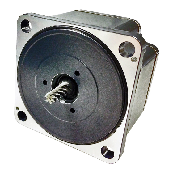
Brushless Motor
BLV Series
R Type
OPERATING MANUAL
Installation and
Connection Edition
Thank you for purchasing an Oriental Motor product.
This Operating Manual describes product handling procedures and safety precautions.
• Please read it thoroughly to ensure safe operation.
• Always keep the manual where it is readily available.
Before using the product
Safety precautions
Precautions for use
Checking the product
Installation
Connection
Guidance
Inspection and maintenance
Appendix
HP-5140-2
Advertisement
Table of Contents

Subscribe to Our Youtube Channel
Related Manuals for Oriental motor BLV Series


Summary of Contents for Oriental motor BLV Series
- Page 1 Inspection and maintenance Connection Edition Appendix Thank you for purchasing an Oriental Motor product. This Operating Manual describes product handling procedures and safety precautions. • Please read it thoroughly to ensure safe operation. • Always keep the manual where it is readily available.
-
Page 2: Table Of Contents
Table of contents Before using the product .........................3 Safety precautions ............................4 Precautions for use ...........................6 Checking the product..........................9 Package contents ................................9 How to identify the product model ........................10 Information about nameplate ..........................11 Products possible to combine ..........................12 Names and functions of parts .......................... -
Page 3: Before Using The Product
Parameters can also be set using the support software. „ Related operating manuals Operating manuals are not included with the product. Download them from Oriental Motor Website Download Page or contact your nearest Oriental Motor sales office. Operating manual name... -
Page 4: Safety Precautions
Safety precautions Safety precautions The precautions described below are intended to ensure the safe and correct use of the product, and to prevent the customer and others from exposure to the risk of injury. Use the product only after carefully reading and fully understanding these instructions. - Page 5 Safety precautions WARNING • If the alarm function (protective function) of the driver is activated, remove the cause before resetting the alarm. Continuing the operation without removing the cause of the problem may result in malfunction of the motor, leading to injury or damage to equipment. •...
-
Page 6: Precautions For Use
Precautions for use Precautions for use This section covers restrictions and requirements the user should consider when using the product. „ Wiring z Connecting a motor and a driver Use the dedicated connection cable (sold separately) when extending the wiring distance between the motor and the driver. - Page 7 If the protective function for the power supply or driver is activated, contact your nearest Oriental Motor sales office. z Use an electromagnetic brake motor in an application of vertical drive such as elevating equipment.
- Page 8 Precautions for use Combination type-hollow shaft flat gearhead The rotation directions of the gearhead output shaft relative to the motor output shaft are as shown in the figures below. Gearhead output shaft Motor output shaft Front Rear z Sliding noise of electromagnetic brake Sliding noise of the brake disk for the electromagnetic brake motor may be generated during operation.
-
Page 9: Checking The Product
Checking the product Checking the product Package contents Verify that the items listed below are included. Report any missing or damaged items to the branch or sales office from which you purchased the product. „ Motor z Combination type-parallel shaft gearhead …... -
Page 10: How To Identify The Product Model
How to identify the product model „ Motor BLMR 6 200 S K M - 10 FR - F Motor type BLMR: BLV Series R Type Motor Frame size 5: 90 mm (3.54 in.) 6: 104 mm (4.09 in.) Output power... -
Page 11: Information About Nameplate
Checking the product Information about nameplate „ Motor Motor model Motor speci cations Serial number Manufacturing date „ Gearhead Gearhead model Manufacturing date Serial number „ Driver Driver model Driver Manufacturing date speci cations Serial number... -
Page 12: Products Possible To Combine
Checking the product Products possible to combine Verify the model name of the purchased product against the model shown on the package label. Check the motor model and the gearhead model against the model name shown on their nameplates, respectively. •... -
Page 13: Names And Functions Of Parts
Checking the product Names and functions of parts „ Motor The figure shows the combination type-parallel shaft gearhead with electromagnetic brake. Motor Gearhead Motor cable Mounting hole (4 places) Output shaft Encoder/electromagnetic brake connector Motor connector „ Driver This section explains the name and function for each part of the driver. I/O signal connector (CN4) USB connector Motor connector (CN2) -
Page 14: Indication Of Leds
Checking the product Indication of LEDs The driver status and the communication status via RS-485 or CAN can be checked using the indication of LEDs. „ PWR/SYS LED The status of the driver can be checked. LED status Description No light The main power is not supplied. - Page 15 Checking the product Blinking state of LED 200 ms 1,000 ms Single flash (Red) 200 ms 200 ms 200 ms 1,000 ms Double flash (Red) 200 ms 200 ms Blinking (White) 200 ms 200 ms 1,000 ms Single flash (White) An example when the red LED (Error LED) and the white LED (Run LED) blink simultaneously is shown below.
-
Page 16: Installation
Installation Installation Installation location The motor and driver are designed and manufactured to be incorporated in equipment. Install them in a well- ventilated location that provides easy access for inspection. The location must also satisfy the following conditions: • Inside an enclosure that is installed indoors (provide vent holes) •... - Page 17 Installation z Removing and assembling the gearhead See the following steps to replace the gearhead or to change the cable outlet position. 1. Removing the gearhead from the motor Remove the hexagonal socket head screws (2 places) assembling the motor and gearhead, and detach the gearhead from the motor.
- Page 18 Installation „ Combination type-hollow shaft flat gearhead A combination type-hollow shaft flat gearhead can be installed by using either its front or rear side as the mounting surface. Using the included mounting screw set, secure through the four mounting holes so that there is no gap between the product and the mounting plate.
- Page 19 Installation z Installing the safety cover After installing a load, attach the included safety cover. The safety cover can be attached to either side. Tightening torque: 0.45 N.m (3.9 lb-in) Mounting screw for safety cover (M3) Safety cover z Removing and assembling the gearhead See the following steps to replace the gearhead or to change the cable outlet position.
-
Page 20: Installing A Load
Installation „ Round shaft type Secure the motor using the hexagonal socket head screws (not supplied) through the four mounting holes. Install so that there is no gap between the product and the mounting plate. Applicable mounting screws Tightening torque Model Screw size [N·m (lb-in)]*... - Page 21 Installation „ Combination type-hollow shaft flat gearhead If a large impact occurs at instantaneous stop or a large radial load is applied, use a stepped load shaft. • Apply grease (molybdenum disulfide grease, etc.) on the surface of the load shaft and inner walls of the hollow output shaft to prevent seizure.
-
Page 22: Permissible Radial Load And Permissible Axial Load
Installation Permissible radial load and permissible axial load Make sure a radial load and axial load applied to the output shaft will not exceed the permissible values shown in the table below. Failure due to fatigue may occur when the bearings and output shaft are subject to repeated loading by a radial or axial load that is in excess of the permissible limit. -
Page 23: How To Install The Driver
Installation „ Combination type-hollow shaft flat gearhead Radial load Axial load 10 mm (0.39 in.) 20 mm (0.79 in.) Distance from mounting surface Permissible radial load [N (lb.)] ∗ Model Permissible axial load Distance from gearhead mounting surface [N (lb.)] Gear ratio 10 mm (0.39 in.) 20 mm (0.79 in.) -
Page 24: Connection
Connection Connection This chapter explains how to connect the driver with the motor, power supplies, and I/O signals. System configuration WARNING For protection against electric shock, do not turn on the power supply until the wiring is completed. Support software Host controller Power supply for communication... -
Page 25: Connecting The Main Power Supply (Cn1)
Connection Connecting the main power supply (CN1) The power supply current capacity varies depending on the motor connected. Insert the connector of the power supply cable into the main power supply connector (CN1) on the driver. The power supply cable LC03D06A (sold separately) is provided. Motor Input power supply voltage Power supply current capacity... -
Page 26: Connecting The I/O Signals (Cn4)
Connection Connecting the I/O signals (CN4) Connect the I/O signal cable, power supply cable for communication, RS-485 communication cable, or CAN communication cable to CN4 according to your method for using. „ How to wire the CN4 connector • Applicable lead wire: AWG26 to 20 (0.14 to 0.5 mm •... - Page 27 Connection • "No.7: CAN_GND," "No.8: 485GND," "No.21: NET-GND," and "No.22: 485GND" are connected to a signal ground (SG). The SG is insulated from "No.13: 0 V" and "Ground for main power supply." • If the power removal function is not used, connect a jumper wire (included) between the terminals as shown in the figure.
- Page 28 Connection „ Connection example with a current sink output circuit Host controller Driver 12 to 30 VDC IN-COM IN0 (ID-SEL0) 6.6 k 10 k IN1 (ID-SEL1) 6.6 k 10 k IN2 (STOP) 6.6 k 10 k IN3 (FREE) 6.6 k 10 k 12 to 30 VDC 10 mA or less→...
- Page 29 Connection „ Connection example with a host controller (RS-485 communication) Host controller Driver 1st unit RS-485 485GND 485GND Driver 2nd unit 485GND 485GND Driver 31th unit 485GND *1 Termination resistor 120 Ω *2 Set the "RS-485 communication termination resistor" parameter to "Enable" with the support software. •...
- Page 30 Connection „ Connection example with a host controller (CAN communication) Host controller Driver 1st unit CAN_H CAN_L CAN_GND Driver 2nd unit CAN_H CAN_L CAN_GND Driver n-th unit CAN_H CAN_L CAN_GND R: Termination resistor Connect the termination resistors (120 Ω, 1/4 W or more) on both ends of a bus. Termination resistors are not included with the product.
- Page 31 Connection „ Connection example with a host controller (power removal function) z Input signal Signal name Specifications HWTO1+ input HWTO1− input 12 to 30 VDC HWTO2+ input HWTO2− input Host contraoller Driver 12 to 30 VDC 6.6 kΩ HWTO1+ 10 kΩ HWTO1- 6.6 kΩ...
-
Page 32: Grounding The Motor
Connection Grounding the motor • Install the motor to a grounded metal plate. • Wires used to ground the motor and the driver must be as thick and short as possible so that no potential difference is generated between the grounding points. •... -
Page 33: Noise Elimination Measures
Connection Noise elimination measures There are two types of electrical noises: One is a noise to invade into the driver from the outside and cause the driver malfunction, and the other is a noise to emit from the driver and cause peripheral equipment malfunction. For the noise that is invaded from the outside, take measures to prevent the driver malfunction. -
Page 34: Conformity To The Emc Directive
The use of the following installation and wiring methods will enable the motor and driver to be compliant with the EMC directive. Refer to p.48 for the applicable standards. Oriental Motor conducts EMC testing on its motors and drivers in accordance with "Example of installation and wiring."... - Page 35 Grounding * Oriental Motor connection cables are used. • The termination resistors are connected on both ends of the CAN communication cable to conduct the testing. • The CAN-Bus cable is used for the CAN communication cable.
-
Page 36: Guidance
Guidance Guidance If you are new to this product, read this section to understand the setting flow of the communication parameters. STEP1 Check of installation and connection STEP2 Connection of termination resistor Check the connection of the termination resistor. ... - Page 37 Guidance STEP 2 Connection of termination resistor Connect a termination resistor for a driver located the farthest away (positioned at the end) from the host controller. There are the following two methods for how to connect a termination resistor. z When a termination resistor inside the driver is used Change the "RS-485 communication termination resistor"...
- Page 38 Guidance STEP 4 Check of communication parameters Start "Starts the simple setting." of the support software. Set the following communication parameters according to the communication parameters of the host controller. If the values are different, change the value of the "Input value" and execute "Reflecting on the driver." If the following communication parameters are different from those of the host controller, execute "Detailed setting..."...
-
Page 39: Setting Of Can Communication
Guidance Setting of CAN communication STEP 1 Check of installation and connection Support software Host controller Power supply for communication Motor Main power supply DC power supply STEP 2 Connection of termination resistor CANopen Driver 1 Driver n master CAN_L CAN-BUS cable CAN_H CAN_GND... - Page 40 Guidance STEP 4 Check of communication parameters Start "Starts the simple setting." of the support software. Set the following communication parameters according to the communication parameters of the host controller. If the values are different, change the value of the "Input value" and execute "Reflecting on the driver." The "Node-ID"...
-
Page 41: Inspection And Maintenance
Inspection It is recommended that periodic inspections are conducted for the items listed below after each operation of the motor. If an abnormality is generated, discontinue any use and contact your nearest Oriental Motor sales office. „ Inspection item z Motor •... -
Page 42: Appendix
Appendix Appendix Timing chart „ Power activation or more 10 s Main power supply or less or less SYS-RDY output or less or less MAIN-PWR output or more Power supply for communication 2 ms or less Whichever 0 s or more or less 100 ms is longer... -
Page 43: Alarm List
Appendix Alarm list Number of Reset using the Alarm code Alarm type Motor excitation* LED blinks ALM-RST input Non-excitation after Position deviation Possible deceleration Overcurrent Not possible Non-excitation Non-excitation after Main circuit overheat deceleration Overvoltage Non-excitation Possible Undervoltage Non-excitation after deceleration Motor overheat Encoder error... -
Page 44: Specifications
Appendix Specifications „ Specifications Motor models in the table below describe a part of the entire name of models. Refer to p.12 for models in details. Motor BLMR5100K BLMR5200K / BLMR6200SK Model Driver BLVD-KRD Rated output power (Continuous) 100 W 200 W Rated voltage 24 to 48 VDC... - Page 45 Appendix „ RS-485 communication specifications Electrical In conformance with EIA-485 characteristics Use twisted-pair wires and keep the total extension distance up to 10 m (32.8 ft.). * Communication Half duplex mode Asynchronous mode (data: 8 bits, stop bit: 1 bit/2 bits, parity: none/even number/odd number) Selectable from 9,600 bps, 19,200 bps, 38,400 bps, 57,600 bps, 115,200 bps, and 230,400 bps Transmission rate (initial value).
- Page 46 Appendix „ Main power supply input voltage and output torque If the input voltage to the main power supply is dropped, the output torque is limited. z 200 W type motor 1.6 (14.1) 24 V 21.6 V 1.4 (12.3) 18 V 1.2 (10.6) 15 V 1 (8.8)
- Page 47 Appendix „ Dimensions Mass: 0.12 kg (0.26 lb.) [Unit: mm (in.)] Ø4.5 [Ø0.177] Thru 65 [2.56] (17.3 [0.68]) 14 [0.55] 55 [2.17] 10 [0.39] Ø4.5 [Ø0.177] Thru...
-
Page 48: Regulations And Standards
Appendix Regulations and standards „ UL Standards, CSA Standards This product is recognized by UL under the UL and CSA Standards. „ EU Directives, UK Regulations z EU Low Voltage Directive/UK Electrical Equipment (Safety) Regulation This product is exempt from the restriction. z EU EMC Directive/UK EMC Regulation EMC testing is conducted on this product under the conditions specified in "Example of installation and wiring"... - Page 50 If a new copy is required to replace an original manual that has been damaged or lost, please contact your nearest Oriental Motor branch or sales office. • Oriental Motor shall not be liable whatsoever for any problems relating to industrial property rights arising from use of any information, circuit, equipment or device provided or referenced in this manual.
Need help?
Do you have a question about the BLV Series and is the answer not in the manual?
Questions and answers