Table of Contents
Advertisement
Quick Links
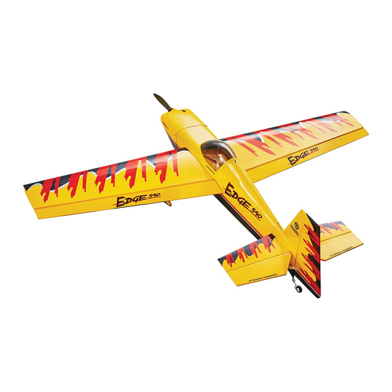
WINGSPAN
58.25 in [1480 mm]
LENGTH
47.25 in [1200 mm]
WING LOADING
20.5 – 23.4 oz/ft
2
[62.5 –71.4 g/dm
WING AREA
590 in
2
[ 38.0 dm
2
]
WEIGHT
84 – 96 oz [2380 – 2720 g]
RADIO
4+ Channel Transmitter
4–6 servos
NOTICE
All instructions, warranties and other collateral documents are
subject to change at the sole discretion of Horizon Hobby, LLC.
For up-to-date product literature, visit www.horizonhobby.com
and click on the support tab for this product.
MEANING OF SPECIAL LANGUAGE
The following terms are used throughout the product literature
to indicate various levels of potential harm when operating this
product:
WARNING: Procedures, which if not properly followed, create
the probability of property damage, collateral damage, and
serious injury OR create a high probability of superficial injury.
CAUTION: Procedures, which if not properly followed, create
the probability of physical property damage AND a possibility
of serious injury.
NOTICE: Procedures, which if not properly followed, create a
possibility of physical property damage AND little or no
possibility of injury.
READ THROUGH THIS MANUAL BEFORE STARTING CONSTRUCTION.
It contains important instructions and warnings concerning the assembly and use of this model.
WARNING: This product may use a lithium polymer (LiPo) battery. Improper handling may result in FIRE! You are responsible for following all
safety precautions as outlined in this instruction manual.
2
]
BATTERY
MOTOR
4S 3300 – 3600 mAh
GP RimFire 32
(42-50-800)
®
.46/EP ARF
ESC 70A
WARNING: Read the ENTIRE instruction manual to
become familiar with the features of the product before
operating. Failure to operate the product correctly can result in
damage to the product, personal property and cause serious injury.
This is a sophisticated hobby product. It must be operated with
caution and common sense and requires some basic
mechanical ability. Failure to operate this Product in a safe and
responsible manner could result in injury or damage to the
product or other property. This product is not intended for use
by children without direct adult supervision. Do not use with
incompatible components or alter this product in any way
outside of the instructions provided by Horizon Hobby, LLC.
This manual contains instructions for safety, operation and
maintenance. It is essential to read and follow all the instructions
and warnings in the manual, prior to assembly, setup or use, in
order to operate correctly and avoid damage or serious injury.
AGE RECOMMENDATION: Not for children under
14 years. This is not a toy.
1
INSTRUCTION
MANUAL
ENGINE
.46 –.55 [7– 9 cc]
.70–.72 [11.5 cc]
2-stroke
4-stroke
Glow Engine
58981 TOWA2024
®
Advertisement
Table of Contents

Related Manuals for Tower Hobbies EDGE 540


Summary of Contents for Tower Hobbies EDGE 540
- Page 1 ® ® INSTRUCTION MANUAL .46/EP ARF WINGSPAN 58.25 in [1480 mm] LENGTH 47.25 in [1200 mm] WING LOADING 20.5 – 23.4 oz/ft [62.5 –71.4 g/dm WING AREA 590 in [ 38.0 dm WEIGHT 84 – 96 oz [2380 – 2720 g] RADIO BATTERY MOTOR...
-
Page 2: Table Of Contents
Follow These Important Safety Precautions knowbeforeyoufl y.org faa.gov/uas 1. Your Edge 540 model should not be considered a toy, but rather a sophisticated, working model that functions very much like a full-size airplane. Because of its performance capabilities, this model, if not assembled and operated... -
Page 3: Engine Safety Precautions
● To stop a glow powered engine, set-up a throttle cut on 7. If you are not an experienced pilot or have not fl own this type of model before, we recommend that you get the your transmitter to completely close the barrel of the assistance of an experienced pilot in your R/C club for carburetor. -
Page 4: Required Items
NEVER use water to try and put out a LiPo fi re. for the Edge 540 Super Aero ARF. NEVER charge or use a battery that is deformed, bent, ❍ (6) Mini servos with at least 50 oz of torque (2-aileron, crushed, swollen, or has any type of visible damage. -
Page 5: Optional Supplies And Tools
Here is a list of optional tools mentioned in the manual that Replacement parts are available from Tower Hobbies for your will help you build the Edge 540 ARF model. Edge 540 ARF model. Our order assistance representatives are ready to answer your questions or to place your order. -
Page 6: Preparation
PREPARATION ❏ 4. Center the aileron servo; a. Connect the servo to the receiver. Use a covering iron set to 300° F with a covering sock to go b. Switch on the transmitter and temporarily connect over the model, tightening the covering where necessary. the ESC and motor battery or a receiver battery to NOTICE: This covering material is printed. - Page 7 ❏ 6. Install the aileron servo using the screws included with the servo. IMPORTANT: Anytime a screw is threaded into wood, fi rst drill a pilot hole, install the screw, then remove the screw and harden the screw hole with thin CA. After the CA has hardened, re-install the screw.
-
Page 8: Join The Wing Panels
Join the Wing Panels ❏ 13. Switch on the transmitter and receiver. Check that the aileron servo arm and aileron are centered. Mark the pushrod where it crosses the aileron servo arm. ❏ 1. Glue the two plywood wing joiners together. ❏... -
Page 9: Install The Main Landing Gear
❏ 4. Apply epoxy to the wing joiner, to all surfaces inside the joiner pocket of each wing half and the root ribs. Insert the ❏ 3. Install the wheel collar. wing joiner in one wing half and join the wing halves together. ❏... - Page 10 ❏ 4. Check that the horizontal stabilizer is parallel with the wing. If it is not, lightly sand the stabilizer slot until it is parallel. ❏ 2. Remove the wing and glue the wing bolt plate onto the wing. ❏ 5.
-
Page 11: Install The Rudder Servo
❏ 7. Check the fi t of the fi n on the fuselage with the CA hinge and tail gear wire installed. Make sure the tail gear wire is aligned with the rudder. ❏ 10. Install the tail wheel. Install the Rudder Servo Note: The elevators will be installed after the rudder control horn is installed. - Page 12 ❏ 3. Glow only: Install the receiver battery switch. ❏ 4. From the remaining hook and loop material used to make the receiver battery strap, make a receiver strap. Place the receiver on foam and secure it in the fuselage with the hook and loop strap.
-
Page 13: Install The Elevator Servo
Single Elevator Servo Install the Elevator Servo ❏ 1. Insert a T-pin into the center of six CA hinges. ❏ 2. Insert the hinges into the trailing edge of the horizontal stabilizer, up to the T-pin. ❏ 1. Install the elevator servo. Harden the servo mount screw holes. -
Page 14: Assemble The Motor Box
Electric Power Only Assemble the Motor Box If a glow engine will be installed, proceed to Engine Installation on page 16. ❏ 4. Glue the four ¼" x ¾" (6mm x 20mm) triangle sticks inside the motor box between the joints between the sides, top and bottom. - Page 15 ❏ 11. Make a hook and loop strap from the remaining hook and loop material. Install it in the battery compartment. Attach a piece of adhesive-backed hook and loop material to the battery tray and the motor battery. ❏ 9. Attach the motor to the front of the motor box. ❏...
-
Page 16: Glow Engine Installation
❏ 15. Cut the covering from over the cooling exit slots in the bottom of the fuselage, behind the wing. ❏ 4. Temporarily mount the engine mount on the fi rewall. Do not tighten the screws completely. Glow Engine Installation ❏... - Page 17 ❏ 10. Glue the short outer pushrod tube, fl ush with the back of the fi rewall, in the throttle pushrod hole. ❏ 6. Position the engine so the thrust washer is 5-1/8"(130mm) ❏ 11. Bend the M2 x 500 mm throttle pushrod as shown from the fi rewall.
- Page 18 ❏ 14. Slide the 5" [127mm] outer pushrod tube and one of the plywood pushrod tube supports on the throttle pushrod. ❏ 17. Install a M3 x 5 machine screw in the screw-lock connector. With the throttle stick centered, position the carburetor barrel so that it is half-open.
-
Page 19: Install The Fuel Tank
Install the Fuel Tank ❏ 3. Attach one of the fuel lines to the carburetor. Install the muffl er and attach the fuel line with the plug (pressure line) to the muffl er. Insert the plug you just removed into the third fuel line. -
Page 20: Apply The Decals
❏ 6. Trim the cowl to fi t over the muffl er exhaust tubes or stock muffl er. Use the same method to trim access holes for the glow plug and the needle-valve. Route the fuel fi ll line ❏ 3. -
Page 21: Get The Model Ready To Fly
GET THE MODEL READY TO FLY Check the Control Directions WARNING: DO NOT install the propeller until instructed to do so. ❏ 1. Switch on the transmitter and then the receiver or connect the fl ight battery to the ESC. Center the trims on the transmitter and the servo arms on the servos. -
Page 22: Set The Control Throws
❏ 3. Measure and set the low rate throws using the dual rates Set the Control Throws on the transmitter. Next, measure and set the high and low rate throws for the rest of the control surfaces the same way. If your radio does not have dual rates, we recommend setting the throws at the high rate settings. -
Page 23: Balance The Model Laterally
❏ 2. With the plane ready to fl y, with an empty fuel tank or motor batteries installed but not plugged in, use a Great Planes C.G. Machine or apply narrow (1/16" [2mm]) strips of tape at the front and rear C.G. locations so you will be able to feel them when lifting the model with your fi ngers to check the C.G. -
Page 24: Ground Check And Range Check
Remember to take off into the wind. When you’re ready, point the model straight down the runway, hold a bit of up The Edge 540 ARF is a great-fl ying sport model that fl ies elevator to keep the tail on the ground to maintain tail wheel smoothly and predictably. -
Page 25: Landing
Once the model is on the runway and has lost fl ying speed, Landing hold up elevator to place the tail on the ground, regaining tail wheel control. To initiate a landing approach, lower the throttle while on the downwind leg. Continue to lose altitude, but maintain FINAL NOTE: Have a goal or fl ight plan in mind each time you airspeed by keeping the nose down as you turn onto the fl y. -
Page 26: Limited Warranty
LIMITED WARRANTY WARRANTY SERVICES What this Warranty Covers – Horizon Hobby, LLC, Questions, Assistance, and Services – Your local hobby (Horizon) warrants to the original purchaser that the store and/or place of purchase cannot provide warranty sup- product purchased (the “Product”) will be free from defects port or service. -
Page 27: Throttle Pushrod Template
can Express, and Discover cards. By submitting any item to Horizon for service, you are agreeing to Horizon’s Terms and Throttle Conditions found on our website http://www.horizonhobby. com/content/service-center_render-service-center. Pushrod Template ATTENTION: Horizon service is limited to Product com- pliant in the country of use and ownership. If received, a non-compliant Product will not be serviced. - Page 28 ® © 2018 Horizon Hobby, LLC. Tower Hobbies, Tactic, and the Tower Hobbies logo, are trademarks or registered trademarks of Horizon Hobby, LLC. The Spektrum trademark is used with permission of Bachmann Industries, Inc. All other trademarks, service marks and logos are property of their respective owners.
Need help?
Do you have a question about the EDGE 540 and is the answer not in the manual?
Questions and answers