Table of Contents
Advertisement
To w e r
®
Hobbies
guarantees
this kit to be
free from defects
in both material and
workmanship
at
the
date of purchase. This
warranty does not cover any
component parts damaged by
use or modification. In no case shall
Tower Hobbies' liability exceed the
original cost of the purchased kit. Further,
Tower Hobbies reserves the right to change
or modify this warranty without notice.
In that Tower Hobbies has no control over the final
assembly or material used for final assembly, no
liability shall be assumed nor accepted for any damage
resulting from the use by the user of the final user-assembled
product. By the act of using the user-assembled product, the
user accepts all resulting liability.
If the buyer is not prepared to accept the liability associated with the
use of this product, the buyer is advised to return this kit immediately in
new and unused condition to the place of purchase.
To make a warranty claim send the defective part or item to Hobby Services at
the address below:
Hobby Services • 3002 N. Apollo Dr. Suite 1 • Champaign IL 61822 • USA
Include a letter stating your name, return shipping address, as much contact information as
possible (daytime telephone number, fax number, e-mail address), a detailed description of
the problem and a photocopy of the purchase receipt. Upon receipt of the package the problem
will be evaluated as quickly as possible.
®
© 2016 Tower Hobbies.
A subsidiary of Hobbico, Inc.
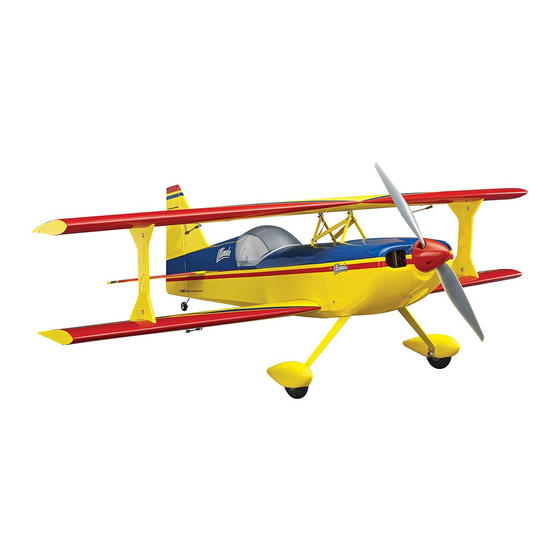
WINGSPAN
45.5 in [1155 mm]
RADIO
4 – 5 channel
6.0 – 7.25 lbs. [2720 – 3290g]
READ THROUGH THIS MANUAL
I N S T R U C T I O N M A N U A L
LENGTH
50 in [1270 mm]
WING AREA
840 sq in [54.2 dm
2
]
WEIGHT
BEFORE STARTING CONSTRUCTION.
IT CONTAINS IMPORTANT INSTRUCTIONS
AND WARNINGS CONCERNING THE
ASSEMBLY AND USE OF THIS MODEL.
TOWER HOBBIES
1
WING LOADING
16 – 20 oz/ft
2
[49– 61 g/dm
POWER
.46 – .55 2-stroke glow,
.72 – .81 4-stroke glow,
RimFire .55 42-60-480,
6S LiPo, 75A ESC
Champaign, Illinois
(217) 398-8970 ext. 5
airsupport@hobbico.com
TOWA2050
2
]
Advertisement
Table of Contents

Related Manuals for Tower Hobbies Ultimate


Summary of Contents for Tower Hobbies Ultimate
-
Page 1: Tower Hobbies
Tower Hobbies reserves the right to change or modify this warranty without notice. READ THROUGH THIS MANUAL In that Tower Hobbies has no control over the final assembly or material used for final assembly, no BEFORE STARTING CONSTRUCTION. liability shall be assumed nor accepted for any damage... -
Page 2: Table Of Contents
Radio/Servos Hobbies Ultimate bipe. In spite of its aerobatic appearance, the Ultimate is a cinch to takeoff, fl y and land and is unexpectedly The Ultimate can be fl own with a 4-channel radio, but a stable. But when you’re ready to lay down some aerobatics computer radio such as the Tactic TTX650 is recommended the Ultimate is ready to respond when it’s time to move the... -
Page 3: Glow Engine & Accessories For Glow
95 watts is required (6S x 4.2 V/cell = 25.2 V x 3.8 A = 95 Watts). The Triton2 EQ is just enough charger with 100 W The Ultimate is suited for a .46 – .55 2-stroke or .72 – .81 output AC and 120 W output DC (GPMM3156). -
Page 4: Kit Inspection
TOWA4050 Fuselage set A Robart Super Stand II (ROBP1402) is also indispensable TOWA4051 Upper wing set for working on your Ultimate. TOWA4052 Lower wing set A covering iron with a cover sock may be required for TOWA4053 Tail surface set... -
Page 5: Preparations
NOTE: If you’re already familiar with iron-on coverings, you Perform the steps 3 through 7 if installing aileron servos may fi nd that the covering on the Ultimate requires less heat in the top wing. than other coverings you’ve worked with. Too much heat causes seams and edges to separate as the covering tightens. - Page 6 6. Use a trim iron to bond the covering down inside the openings. 10. If powering your Ultimate with a glow engine, fuelproof any areas that may be exposed to raw fuel or oily engine 7. Cut the covering from the servo arm openings and...
-
Page 7: Assemble The Wings
But then at least a mirroring the first 7-channel receiver would be required and all the additional and drill the holes servo extensions to connect each one to the receiver. - Page 8 If installing all four aileron servos, this is what the servos and hatch covers should look like. 5. Connect the bottom aileron servos to your receiver (with or without a Y-harness; whichever is your preference) with a battery and turn on your transmitter to power up the system so you can operate the servos.
-
Page 9: Hook Up The Ailerons
10. Pull the other end of the Y-harness through the other side of the wing and mount the other hatch. Hook Up the Ailerons 3. If not installing aileron servos in the top wing, mount a small control horn to the top surface of the bottom ailerons in the location illustrated in the image above and in the Refer to this image while mounting the aileron servos illustration on the bottom of the column to the left. - Page 10 B. Once the stab is centered, insert pins into the trailing edge tightly against both sides of the fuselage to lock the trailing edge into place. 3. Temporarily bolt the bottom wing to the fuselage with the two included nylon wing bolts. Slide the horizontal stabilizer into position and view the model from behind.
-
Page 11: Hinge The Elevators And Rudder
5. Remove one of the pins from the trailing edge and slide Hinge the Elevators and Rudder out the stab. Install the elevator joiner wire into the stab slot in the fuselage, making certain to keep the correct orientation so the elevators will align when refi tted to the joiner. 6. - Page 12 4. Remove the elevators. Add epoxy into the holes in the elevators for the joiner wires. Rejoin the elevators to the stab and joiner wire and wipe away excess epoxy. 5. Use a thin applicator tip to apply 6 drops of thin CA to the top and bottom of each hinge waiting a few seconds between drops for the hinges to absorb the CA.
-
Page 13: Hook Up The Elevator And Rudder
Hook Up the Elevator and Rudder 3. With the surfaces centered, mark, bend and cut the pushrods and connect them to the servos. You can bend and cut the pushrods while they are in the fuselage, but it will be easier to cut and bend them out of the fuselage (but then the clevises will have to be temporarily removed so the pushrods can be reinserted from the front of the guide tubes). -
Page 14: Mount The Esc
Mount the ESC 3. Remove the template from the fi rewall. Drill 1/16" [1.6mm] pilot holes through the fi rewall at the marks. Enlarge the holes with a 13/64" (or 7/32") drill. 1. You may copy the battery and ESC installation shown in the manual, or do it another way if you have a different ESC. - Page 15 a battery strap (like one of the straps shown on page 18) from the included Velcro strips and mount the battery to the battery tray. 5. If the motor mount bolts protrude from the back of the fi rewall, cut two 3" [80mm] pieces from the included 1/4" x ¼"...
-
Page 16: Mount The Engine
Mount the Engine The process for mounting a 4-stroke and a 2-stroke are the same, but most of the instructions show a 4-stroke. Where necessary or helpful, photos and notes for installing a 2-stroke are also provided. 4. If tapping threads, use a 3mm tap to thread the hole – if care is used you can chuck the tap in a hand drill to make the procedure easier and faster. - Page 17 9. If neither template matches the spacing of the mount on 12. Remove the template from the fi rewall. Drill 1/16" your engine, you can make your own template out of one of [1.6mm] pilot holes through the fi rewall at the pinpoints. the existing ones.
-
Page 18: Install The Fuel Tank
rolling them on your workbench under a hobby knife blade. Option: Insert the third aluminum tube through the stopper and attach another pickup line and clunk (not included) for a fueling/defueling line so you won’t have to detach the fuel line from the engine to fuel and as you will with a single-line. -
Page 19: Hook Up The Throttle
5. Install the fuel tank tray into the fuselage guiding the fuel lines out the hole in the fi rewall—make sure the front of the tray keys into the short balsa sticks right behind the fi rewall to hold the front of the tray down. Position the tray as far forward as possible without causing the lines to kink against the engine, then secure the tray with one of the fi nger-turn ¼-20 nylon bolts included. -
Page 20: Mount The Cowl
4. While we’re still working “under the hood,” mount the muffl er and connect the fuel line to the carb and the vent line to the pressure tap off the muffl er (the dangling fuel line in the photo will be for fueling/defueling). Mount the Cowl Disregard the landing gear and wings that appear in following images. - Page 21 2. Position the cowl onto the fuselage over the engine/motor and install the spinner back plate onto the prop shaft with a prop and prop nut. (For glow engines, temporary removal of the muffl er and needle valve may be required to fi t the cowl.). 5.
-
Page 22: Finish The Radio Installation
the receiver where desired. Use tape to hold the receiver antennas perpendicular to each other as specifi ed in the instructions that came with your radio control system. 10. If you’ve mounted an electric motor with the adjustable brushless motor mount, move the motor forward the distance of the desired spinner gap. -
Page 23: Mount The Main Landing Gear
Mount the Main Landing Gear 1. Fasten the wheel axles to the main landing gear with an 8mm lock nut – be certain to use threadlocker on the threads as the threaded portion of the axles does not engage the nylon locking part in the nuts. -
Page 24: Attach The Belly Pan
Attach the Belly Pan 1. Mount the bottom wing to the fuselage with the included ¼ - 20 x 1" nylon wing bolts and 5/8" x ¾" [16 x 19mm] wing bolt plates. M3 x 5 M3 x 5 M3 x 8 2. -
Page 25: Assemble The Canopy Hatch
Assemble the Canopy Hatch You’ll see the wings are attached in the following images, but we determined it was easier to work on the canopy before mounting the wings. If using a brushless motor, the cockpit hatch may be held to the fuselage with M3 screws and washers through both sides of the fuselage into the tabs, or with the rubber band hook and a rubber band. -
Page 26: Mount The Wings
4. Mount the cockpit hatch to the fuselage with a rubber band around the hooks, or cut the covering from the screw holes in the fuselage sides for the hatch screws and mount the cockpit with two M3 x 14 Phillips screws and washers. 5. - Page 27 A clean way to cut the hole for the servo wire is to cut two holes with a 1/8" [3.0mm] brass tube sharpened on the end, then join the holes by removing material between them as shown in the image. Or just cut carefully with a hobby knife. Shorter (top) Front...
- Page 28 two knurled thumb nuts onto the stud to act as a stop-nut and turn them to turn in the stud. The studs should stop when they get about halfway in. 4-5/8" [117mm] Bottom of top wing 5. Insert the four 3 x 12mm alignment pins into the wing struts, then securely glue them into place with a few drops of thin CA.
- Page 29 is suggested). Guide the open end of the Y-harness (or servo extension) up through the fuselage so it will be accessible from inside the cabin for connecting to the extension coming down from the top wing when the plane is upright. Mount the bottom wing to the fuselage.
-
Page 30: Make The Aileron Pushrods
Make the Aileron Pushrods Skip this section if you’re using four aileron servos. 1/4" 1/4" [6mm] [6mm] 5-7/8" [150mm] 1. Make two 5-7/8" [150mm] pushrods by cutting an equal amount from both ends of a 6-3/8" [160mm] pushrod. Use a metal fi le or a cutoff wheel to remove any burrs from the cut ends of the wire. -
Page 31: Check The C.g
Ultimate balanced in the middle or forward half of the range. 3. If the Ultimate doesn’t balance where specifi ed, relocate the receiver battery or motor battery or add stick-on lead ballast to the nose or tail to achieve the correct C.G. -
Page 32: Propeller Selection For A Brushless Motor
Do not throw anything into the propeller of a running engine. But we’ve also fl own the Ultimate with a 16 x 8E and a 15 x 10E. Of the props tested, the 16 x 8 E is preferred, but the peak WARNING: For brushless electric motors, never have the current draw will be a little higher (around 65 A). -
Page 33: Battery Precautions
you have fl own enough times and gathered enough data to Battery Precautions make the calculations for setting maximum fl ight time (see the worksheet on page 32). When the timer sounds, land. Before mounting the motor and setting up the ESC and When you charge the battery note how much capacity it battery, read the following important battery precautions: took to recharge (indicating how much capacity (mAh) was... -
Page 34: Range Check
2) I will not fl y my model aircraft higher than approximately 400 feet within 3 miles of an airport without notifying the 11.1V airport operator. I will give right-of-way and avoid fl ying in the (3-Cell) proximity of full-scale aircraft. Where necessary, an observer shall be utilized to supervise fl ying to avoid having models fl y in the proximity of full-scale aircraft. -
Page 35: Flying
As mentioned in the introduction, in spite of its aerobatic stall characteristics at a high altitude where there is plenty of design the Ultimate is an easy fl yer. If you’ve prepared your time and altitude to recover. The Ultimate doesn’t exhibit any... - Page 36 ® © 2016 Tower Hobbies. A subsidiary of Hobbico, Inc. TOWA2050...
Need help?
Do you have a question about the Ultimate and is the answer not in the manual?
Questions and answers