Table of Contents
Advertisement
Quick Links
I N S T R U C T I O N M A N U A L
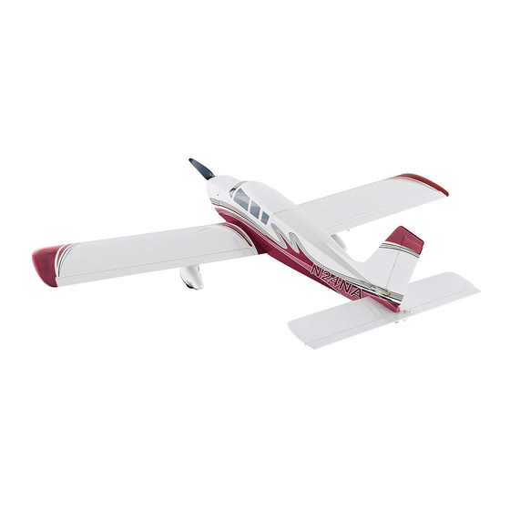
WINGSPAN
LENGTH
WING LOADING
To w e r
®
43.2 in [1097mm]
33.8 in [859 mm]
17.2 – 19.2 oz/ft
[52.5 – 58.6 g/dm
]
Hobbies
2
2
guarantees
MOTOR
this kit to be
free from defects
WING AREA
RimFire .10 35-30-1250 kV
in both material and
workmanship
at
the
318.0 in
2
[20.51 dm
2
]
3S 11.1V 2200 mAh – 3200 mAh LiPo
date of purchase. This
40A ESC
warranty does not cover any
component parts damaged by
WEIGHT
RADIO
use or modification. In no case shall
Tower Hobbies' liability exceed the
38.0 – 42.3 oz [1077–1199g]
4 – 5 channels, 4 servos
original cost of the purchased kit. Further,
Tower Hobbies reserves the right to change
or modify this warranty without notice.
READ THROUGH THIS MANUAL
In that Tower Hobbies has no control over the final
assembly or material used for final assembly, no
BEFORE STARTING CONSTRUCTION.
liability shall be assumed nor accepted for any damage
IT CONTAINS IMPORTANT INSTRUCTIONS
resulting from the use by the user of the final user-assembled
AND WARNINGS CONCERNING THE
product. By the act of using the user-assembled product, the
user accepts all resulting liability.
ASSEMBLY AND USE OF THIS MODEL.
If the buyer is not prepared to accept the liability associated with the
use of this product, the buyer is advised to return this kit immediately in
new and unused condition to the place of purchase.
TOWER HOBBIES
To make a warranty claim send the defective part or item to Hobby Services at
the address below:
Champaign, Illinois
Hobby Services • 3002 N. Apollo Dr. Suite 1 • Champaign IL 61822 • USA
(217) 398-8970 ext. 6
Include a letter stating your name, return shipping address, as much contact information as
possible (daytime telephone number, fax number, e-mail address), a detailed description of
airsupport@hobbico.com
the problem and a photocopy of the purchase receipt. Upon receipt of the package the problem
will be evaluated as quickly as possible.
®
© 2018 Tower Hobbies.
A subsidiary of Hobbico, Inc.
TOWA2200 EP ARF / TOWA2202 EP RxR
Advertisement
Table of Contents

Related Manuals for Tower Hobbies TOWA2200


Summary of Contents for Tower Hobbies TOWA2200
-
Page 1: Tower Hobbies
Tower Hobbies reserves the right to change or modify this warranty without notice. READ THROUGH THIS MANUAL In that Tower Hobbies has no control over the final assembly or material used for final assembly, no BEFORE STARTING CONSTRUCTION. liability shall be assumed nor accepted for any damage... - Page 2 INTRODUCTION LiPo 30C 3S 11.1V 3200 Star (ONXP1953) Programmable ESC 40A BL 2S-6S (GPMM2140) Thank you for purchasing the Tower Hobbies Cherokee EP. APC 9x6E Thin Electric Propeller (APCQ4118) This Cherokee is intended for electric power only, so the structure has been lightened accordingly to make it a nice LiPo Battery Charger little scale fl yer.
-
Page 3: Electric Motor Safety Precautions
ALWAYS charge a LiPo battery in a fi reproof location. ELECTRIC MOTOR ALWAYS balance charge the battery pack. SAFETY PRECAUTIONS ALWAYS store and transport LiPo batteries in a fi reproof container away from combustible materials. WARNING! A spinning propeller has the potential to cause serious and permanent injury. -
Page 4: Kit Contents
KIT CONTENTS SPARE PARTS TOWA4100 Wing Set TOWA4101 Fuselage TOWA4102 Tail Surfaces Set TOWA4103 Cowl TOWA4104 Hatch TOWA4105 Landing Gear Set TOWA4106 Wheel Pants Set TOWA4107 Decals GPMA4045 1-3/4" White Spinner 1. Cowl 5. Left Wing 9. Wing Joiners 13. Spinner 2. -
Page 5: Assemble The Wing
3. Tape the ends of the servo strings that are inside the wings to the outside of the wings. Test-fi t the wing halves together with the wing joiner and the alignment pin. Make any adjustments necessary for a good fi t. NOTE: Even though you may be using 30-minute epoxy, some brands of epoxy harden faster than others and time seems to fl y when working time is limited, so make sure you... -
Page 6: Hook Up The Ailerons
to wipe away excess epoxy as you proceed. Allow the epoxy to fully harden before removing the clamps and tape. 7. After the epoxy has hardened, remove the clamps and carefully peel off the tape. Any residual tape adhesive may be cleaned with naptha (lighter fl uid) and areas of the covering that may have lifted from removing the tape may be retightened with your covering iron. -
Page 7: Mount The Landing Gear
and cut the pushrod. Then, hook up the aileron with a 90-degree pushrod connector on the servo arm as shown. 9. Hook up the aileron servo in the right wing the same way. Mount the Landing Gear 5. Fasten the gear to the pant with a strap and a M2.5 x 10 washer-head Phillips wood screw. -
Page 8: Assemble The Fuselage
3. If necessary, adjust the slot for the stab in the fuselage to get the stab horizontally aligned with the wing. Usually though, all that will be required is a small amount of weight on the high side of the stab. 4. -
Page 9: Mount The Nose Gear
8. After the epoxy gluing the stab and fi n to the fuselage Mount the Motor & ESC has hardened, remove the wing. Mount the Nose Gear 1. Mount the motor to the motor mount box with four M3 x 10 Phillips machine-thread screws, M3 lock washers and fl at washers with a touch of threadlocker on the threads. -
Page 10: Mount The Cowl
3 . Do not install the propeller. Power up the ESC and use the transmitter to run the motor to make sure it turns counter-clockwise when viewed from the front. If the motor turns the wrong direction, disconnect the battery, and switch any two of the three motor wires with each other. -
Page 11: Hook Up The Elevator And Rudder
Hook Up the Elevator and Rudder 1. Cut one of the 27" [680mm] pushrods to a length of 18-1/2" [470mm] and the other to 17-1/2" [445mm] by cutting off the unthreaded end. Thread a nylon clevis about fi fteen 10. Reposition and align the cowl. Drill 1/16" [1.6mm] full turns onto each pushrod and connect each one to a holes into the fuselage through each screw hole in the cowl. - Page 12 7. Drill 1/16" [1.6 mm] holes in the servo tray for the elevator servo and mount the servo with the mounting hardware that 3. Mount the rudder horn the same way. came with it. 7/16" 11/32" 11/32" [ 9 mm] [11 mm] [9 mm ] Rudder/nose...
-
Page 13: Final Assembly
9. Remove the propeller before powering up the These are the recommended control surface throws: radio. Connect the servos to your receiver, power up the radio, center the servos and adjust the clevises on the pushrods HIGH RATE LOW RATE so the elevator and rudder are centered. -
Page 14: Set The Fail Safe And The Motor Brake
Set the Fail Safe and the Motor Brake FAIL SAFE: While you have your radio operational and without the propeller mounted, now would also be a good time to set and check the Fail Safe function of your transmitter. Refer to the instructions that came with your radio control system to set Fail Safe on the throttle channel so that, in the event of signal loss, the motor will stop. -
Page 15: Balance The Model Laterally
through and under the battery tray and cut the strap to the correct length to secure the battery. 9. Double-check the C.G. and, if necessary, reposition the 38 mm 1-1/2" battery and adjust any marks you may have made, noting 56 mm 2-3/16"... -
Page 16: Flying
B / A E / C B/1000 / (A/60) Flight Time Recharge Battery Target Capacity Recommended Avg. In-Flight mAh/minute (.10 ths ) Capacity Capacity to Use in Flight Flight Time Current ® © 2018 Tower Hobbies. A subsidiary of Hobbico, Inc. TOWA2200/2202...
Need help?
Do you have a question about the TOWA2200 and is the answer not in the manual?
Questions and answers