Table of Contents
Advertisement
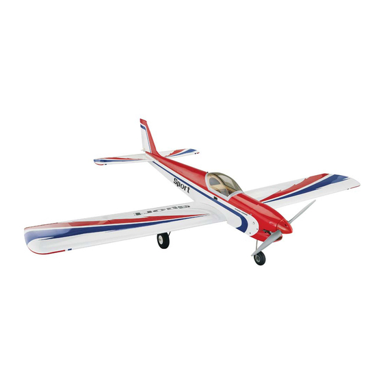
I N S T R U C T I O N M A N U A L
WINGSPAN
LENGTH
WING LOADING
To w e r
60.2 in [1529mm]
48.7 in [1237mm]
17.49 – 18.46 oz/ft
2
[53 – 56 g/dm
2
]
®
Hobbies
guarantees
RADIO
POWER
this kit to be
WING AREA
free from defects
4 – 5 channel
.46 – .55 cu in [7.5 – 9.0cc] 2-stroke glow,
in both material and
592.8 sq in [38.24 dm
2
]
workmanship
at
the
4 – 5 servos
.70 cu in [11.5cc] 4-stroke glow,
date of purchase. This
Motor: 1.65" [42mm] 925W,
warranty does not cover any
WEIGHT
component parts damaged by
Castle Creations Edge Lite 75 ESC (not included)
use or modification. In no case shall
72 – 76 oz. [2041– 2155g]
ESC: 60A - 4S (not included)
Tower Hobbies' liability exceed the
original cost of the purchased kit. Further,
Tower Hobbies reserves the right to change
or modify this warranty without notice.
READ THROUGH THIS MANUAL
In that Tower Hobbies has no control over the final
assembly or material used for final assembly, no
BEFORE STARTING CONSTRUCTION.
liability shall be assumed nor accepted for any damage
IT CONTAINS IMPORTANT INSTRUCTIONS
or injury resulting from the use by the user of the final
AND WARNINGS CONCERNING THE
user-assembled product. By the act of using the user-assembled
product, the user accepts all resulting liability.
ASSEMBLY AND USE OF THIS MODEL.
If the buyer is not prepared to accept the liability associated with the
use of this product, the buyer is advised to return this kit immediately in
new and unused condition to the place of purchase.
TOWER HOBBIES
To make a warranty claim send the defective part or item to Hobby Services at
the address below: (Visit hobbyservices.com for more information.)
Champaign, Illinois
Hobby Services • 3002 N. Apollo Dr. Suite 1 • Champaign IL 61822 • USA
(217) 398-8970 ext. 6
Include a letter stating your name, return shipping address, as much contact information as
possible (daytime telephone number, fax number, e-mail address), a detailed description of
airsupport@hobbico.com
the problem and a photocopy of the purchase receipt. Upon receipt of the package the problem
will be evaluated as quickly as possible.
®
© 2016 Tower Hobbies.
A subsidiary of Hobbico, Inc.
TOWA2030
1
Advertisement
Table of Contents

Related Manuals for Tower Hobbies SPORT


Summary of Contents for Tower Hobbies SPORT
-
Page 1: Tower Hobbies
Tower Hobbies reserves the right to change or modify this warranty without notice. READ THROUGH THIS MANUAL In that Tower Hobbies has no control over the final assembly or material used for final assembly, no BEFORE STARTING CONSTRUCTION. liability shall be assumed nor accepted for any damage... -
Page 2: Table Of Contents
Glow Engine (HCAM6411)* On-off receiver switch (TACM2000)* The Sport is suited for a .45 - .55 2-stroke or .70 4-stroke. The O.S. Max .46AXII (OSMG0548) is illustrated in this manual. Servos nowadays are smaller and stronger, so we’ve designed the servo mounts in the Sport to accommodate mini servos,... -
Page 3: Brushless Electric Motor
The electric setup for the Sport is straightforward: a Great the model was removed from the box. The 21 Century iron Planes Electrifl y RimFire .32 on a 13 x 8 E prop with a minimum... -
Page 4: Contents
(especially on the sheet balsa tail surfaces) press down on the iron to thoroughly bond the covering to the balsa NOTE: The covering on your Sport requires less heat than underneath. If the covering blisters up over balsa and cannot you may be used to if you’re already familiar with iron-on... -
Page 5: Assemble The Wing
3. Use the string to pull the aileron servo wire through the wing and fi t the servo into the servo openings. 3. If powering your Sport with a glow engine, apply a fi lm of epoxy or CA to edges of the covering around the nose and fi rewall to seal from fuel and exhaust residue. -
Page 6: Mount The Landing Gear
Mount the Landing Gear Landing gear angled back. 3. Use two fl at landing gear straps as a guide to drill 3/32" [2.4mm] holes into the landing gear block in the left wing. 4. Enlarge the holes in the two landing gear straps with a 1/8"... -
Page 7: Assemble The Fuselage
2. Stack two or three paper towels over each other and cut them into small squares. Have the paper towel squares and denatured alcohol ready for epoxy clean up while joining the wing in the next few steps. 4. Use plenty of masking tape to tightly clamp the wing halves together and use a small clamp to clamp the front of the wing together at the leading edge tab. -
Page 8: Install The Pushrods And Mount The Nose Gear
2. If powering your Sport with a brushless motor, cut the 6. Remove the stab and fi n and prepare for gluing into covering from the air exit vents in the bottom of the fuselage. the fuselage. Typically, the fi n and stab are glued into the For a better fi nish, cut the covering about 1/32"... - Page 9 5. If installing a brushless motor, cut the rest of the way CORRECT INCORRECT through the partially cut air inlet in the fi rewall and remove the piece as shown in the photo in the following step. Hinge Line Hinge Line 6.
-
Page 10: Mount A Glow Engine
Mount a Glow Engine If installing a brushless motor, skip to Assemble the EP Motor Mount Box on page 12. The engine illustrated in the instruction manual is mounted inverted. This is the easiest, most-convenient and most- streamlined way to mount the engine, but the exhaust is aimed directly at the wing. -
Page 11: Install The Fuel Tank
Install the Fuel Tank 7. Tap the threads into the holes—this may be easily and quickly done with a drill. 8. Mount the engine mount to the fi rewall and mount the engine to the mount. 1. Loosen the screw in the stopper in the fuel tank and take out the stopper/fuel line assembly. -
Page 12: Assemble The Ep Motor Mount Box
5. Cut one of the fuel lines (from either of the two tubes on the bottom of the tank) to the correct length to fi t the carburetor. Leave the other two lines (one for fueling/defueling, the other for the pressure/vent line from the muffl er) the length they are now –... -
Page 13: Mount The Brushless Motor
5. Glue the triangle reinforcements around the back and front—use medium CA and stick them into place with a hobby knife. Reinforce all glue joints where necessary. 3. Before using any glue, test fi t the sides, top, bottom, front and back of the motor mount box together. Make sure the arrows on the front and back point toward the top of the 6. -
Page 14: Cut The Cowl
Cut the Cowl A No. 569 or 570 Dremel grout removal bit and a sanding drum are indispensable for easily and accurately cutting a fi berglass cowl. Always wear eye and breathing protection when cutting fi berglass. 2. Assemble the “X” mount and the propeller shaft to your motor. - Page 15 5. There’s no really fast, easy way to cut holes in a cowl that fi ts tightly around an engine like this. The best way is to install the cowl and, little by little, mark, cut and re fi t the cowl as necessary until it will go on over the engine.
- Page 16 7. Continue to fi t, mark and cut the cowl until you can get it to fi t. 8. Once you can get the cowl to fi t all the way over the engine, mark and cut the hole for the muffl er. This cowl was cut so that the muffl er has to be installed after the cowl (tightening the muffl er bolts through holes cut in the opposite side of the cowl), but another way is to cut all the way to the...
-
Page 17: Mount The Cowl
11. Here’s a close-up of the fi nished cowl. Mount the Cowl Now that the cowl can be positioned all the way over the engine and muffl er, it may be mounted to the fuselage. 9. Cut any other holes necessary for the nose gear, fueling line, muffl er pressure line, glow plug igniter, etc. - Page 18 3. If necessary, enlarge the hole in the back plate of the 6. Once the screw hole locations have been marked, spinner to fi t the crank shaft or propeller shaft, then fi t the double-check to be sure the cowl is positioned to align with the back plate onto the engine/motor.
-
Page 19: Install The Radio
6. Cut the nose steering pushrod to the correct length and Install the Radio bend it as necessary to connect the rudder servo. Connect the pushrod to the servo arm using a screw-lock connector, 1. If necessary, enlarge the cutout in the servo tray to an M3 set screw and a retainer. -
Page 20: Check The C.g
(but less-experienced pilots should 3. Once you have the nose wheel centered and the perform fi rst fl ights with the Sport balanced in the middle or carburetor arm working properly, tighten the set screws in forward half of the range (slightly nose heavy). -
Page 21: Balance The Model Laterally
– after each fl ight (or any time after running the motor) always disconnect the battery before turning off 1. Lift the Sport several times by the propeller shaft and the transmitter. And when ready to fl y (or whenever running the tail to see if one wing drops. -
Page 22: Battery Precautions
Before mounting the motor and setting up the ESC and battery, read the following important battery precautions: IMPORTANT: If using multiple battery packs that are connected with an adapter, never charge the batteries together through the adapter. Always charge each battery pack separately. -
Page 23: Range Check
Model Aeronautics Safety Code. For the complete Safety Simply fl y the Sport within your capabilities and take it easy Code refer to Model Aviation magazine, the AMA web site for the fi rst couple of fl ights to give yourself time to become or the Code that came with your AMA license. - Page 24 E / C B/1000 / (A/60) FORMULAS Flight Time Recharge Battery Target Capacity Recommended Avg. In-Flight mAh/minute (.10 ths ) Capacity Capacity to Use in Flight Flight Time Current ® © 2016 Tower Hobbies. A subsidiary of Hobbico, Inc. TOWA2030...
Need help?
Do you have a question about the SPORT and is the answer not in the manual?
Questions and answers