Table of Contents
Advertisement
Quick Links
Download this manual
See also:
Manual
Advertisement
Table of Contents

Subscribe to Our Youtube Channel
Related Manuals for Fischer Panda 5000i PMS


Summary of Contents for Fischer Panda 5000i PMS
-
Page 1: Generator Manual
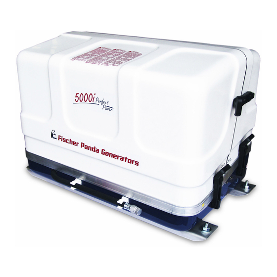
Power - wherever you are Generator manual Panda 5000i PMS Super silent technology 230V 50Hz 5kVA 120V 60Hz 5kVA Fischer Panda GmbH Panda_5000i_PMS_eng.R01 9.12.10... -
Page 2: Current Revision Status
Duplication and change of the manual is permitted only in consultation with the manufacturer! Fischer Panda GmbH, 33104 Paderborn, reserves all rights regarding text and graphics. Details are given to the best of our knowledge. No liability is accepted for correctness. Technical modifications for improving the product wit- hout previous notice may be undertaken without notice. -
Page 3: Table Of Contents
Panda Transport Box ..................... 30 3.2.1 Bolted Fischer Panda Transport Box ................30 3.2.2 Fischer Panda Transport Box with metal tab closure ............30 3.2.3 Opening the MPL sound insulation capsule ..............30 3.2.4 Opening the GFK sound insulation capsule ..............31 Transport and Loading/Unloading ................ - Page 4 Components ........................36 Range of operation ......................37 3.6.1 Main features of the Panda 5000i ..................37 Panda 5000i PMS generator ..................39 Type plate at the generator .................... 39 Description of the Generator ..................40 4.2.1 Right Side View ......................... 40 4.2.2...
-
Page 5: Seite/Page
Generator DC system installation ................. 73 5.8.1 Connection of the starter battery block ................73 5.8.2 Connection of the DC starter battery ................. 74 5.8.3 Fuse ..........................76 5.8.4 Installation of the iControl panel - See iControl Manual ............ 76 Generator AC System Installation ................ - Page 6 7.6.7 Motor runs in off position ....................104 7.6.8 Motor stops by itself ......................104 7.6.9 Sooty, black exhaust ....................... 104 7.6.10 Generator must be shut off immediately if: ..............104 Generator Tables ......................105 Cable cross section ...................... 105 Diameter of conduits ....................105 Technical Data ......................
-
Page 7: Panda_5000I_Pms_Eng.r01 - Kapitel/Chapter 1: Seite/Page
10.9.2 Generator Spezifikation ....................130 10.10PMGi protections ......................131 10.10.1 Overload - switch point ....................131 10.10.2 Short circiut ........................131 9.12.10 Panda_5000i_PMS_eng.R01 - Kapitel/Chapter 1: Seite/Page 7... - Page 8 Seite/Page 8 Panda_5000i_PMS_eng.R01 - Kapitel/Chapter 1: 9.12.10...
-
Page 9: General References And Regulations
A water-cooled Fischer Panda generator, with the same drive motor, produces 15 % more effective output than the majority of conventional generators. This superiority in efficiency also ensures a fuel saving to the same extent. -
Page 10: Safety First Symbols
General References and Regulations 1.1 Safety first symbols These symbols are used throughout this manual and on labels on the machine itself to warn of the possibility of per- sonal injury. Read these instructions carefully. It is essential that you read the instructions and safety regulations before you attempt to assemble or use unit. - Page 11 General References and Regulations Proscription!: Do not touch Berühren der entsprechenden Teile und Anlagen verboten Warning!: Automatic start. Generator can be started by an external signal Warning!: High voltage / danger by electricity - These symbols refer to electrical danger and points to special warnings, instructions and advices, which must be noticed.
- Page 12 General References and Regulations Warning!: Risk of explosion Warning of materials, which can lead to explosions under certain conditions - e.g. heat or ignition sources Warning!: Hot surface Surfaces and substances may be hot. Danger of burn / scalding Warning!: Danger carrosive material - contermi- Warning of materials, which cause corrosive damage during contact.
- Page 13 General References and Regulations Warning!: Hearing damage Warning!: Magnetic field Warning!: High pressure Instruction!: Wear personal protective equip- Protective clothing is close fitting, with low resistance to tearing, with narrow sleeves and without protruding parts. It mainly provides protection against ment (PPE) being entangled by moving machine parts.
- Page 14 General References and Regulations Instruction!: Read the manual instructions Read and consider the regulations, safety instructions and installation guide- lines of manual, in order to avoid dangers and accidents. You protect yours- elf and the generator. Instruction!: Environmental protection Environmental protection is the protection of our habitat. For you and your children Seite/Page 14 General.R01.1 - Kapitel/Chapter 1: General References and Regulations...
-
Page 15: Tools
General References and Regulations Tools This symbols are used throughout this manual to show which tool must be used at maintenance or installation. Spanners SW X = required size X mm Hook wrench for oil filter Screw driver, for slotted head screws and for recessed head screws Multimeter, multimeter with capacitor measuring Socket wrench set Hexagon wrench keys... - Page 16 General References and Regulations Current clamp (DC for synchron generators; AC for asynchron generators) Torque wrench Seite/Page 16 General.R01.1 - Kapitel/Chapter 1: General References and Regulations 9.12.10...
-
Page 17: Customer Registration And Guarantee
2. The installation certificate must be despatched within two weeks of use to Fischer Panda. 3. The official guaranty confirmation will be completed by Fischer Panda after receipt and sent to the customer. 4. A guaranty must be shown to make any claims. -
Page 18: Safety Instructions - Safety First
General References and Regulations 1.5 Safety instructions - Safety first! 1.5.1 Safe operation Careful operation is your best assurance against an accident. Read and understand this manual carefully before operating the engine. All operators, no matter how much experience they may have, should read this and other related manuals befor operating the generator or any equipment attached to it. -
Page 19: Safe Handling Of Fuel And Lubricants - Keep Away From Fire
General References and Regulations 1.5.5 Safe handling of fuel and lubricants - Keep away from fire Keep away open fire from fuels and lubricants. Always stop the generator before refueling and/or lubrivating and protect against unintentional starting. Do not smoke or allow flames or sparks in your work area. Fuel is extremely flammable and explo- sive under certain conditions. -
Page 20: Keep Hands Away From Rotating Parts
Anti-freeze contains poison. Wear rubber gloves to avoid personal injury. In case of contact with skin, whash it off immideately. Do not mix different types of Anti-freeze. The mixture can produce chemical reactioncausing harmful substances. Use approved or genuine Fischer Panda Anti- freeze. -
Page 21: Warning And Caution Labels
General References and Regulations 1.5.10 Implementation of security and maintenance Disconnect the battery from the generator before conducting service. Put a „DO NOT OPERATE“ tag on the remote control panel to avoid accidental starting. Disconnect any automatic starter device, e.g. battery monitor to prevent automatic starting. To avoid sparks from an accidental short circuit always disconnect the battery´s ground cable (-) first and connect it last. -
Page 22: Ground Wire
General References and Regulations 1.6.1.1 Protective grounding and potential equalisation In the low voltage board for current supply of the consumers therefore a protective conductor is grounded and connected with electrically conductive objects. The connection with an outer conductor with these object then leads to the earth fault. -
Page 23: Recommended Starter Battery Size
General References and Regulations 1.6.1.4 Safety instructions concerning the cables Cable Type It is recommended is that the cable used be UL 1426 (BC-5W2) compliant, with Type 3 stranding (ABYC Section E- Cable Size The cable size must be selected taking into account the amperage, voltage and conductor length (from the positive power source connection to the electrical device and back to the negative power source connection. -
Page 24: Safety Instructions For The Handling With Batteries
Battery poles must be protected against short circuits by error. Inside the capsule of the Fischer Panda Generator the battery positive line must be protected against heat and vibration by a suitable conduit or sheath and must be routed that way it is not touching any area that will get hot under normal operation like entire engine itself, exhaust elbow and exhaust manifold or exhaust lines or the V-belt and pulleys. - Page 25 The vibrating devices must be regulary checked about scour points and flaw in the isolation. Attention !! For battery charge generators (Fischer Panda AGT-DC)! Check before installation if the battery bank voltage correspond with the generator output voltage 9.12.10...
- Page 26 General References and Regulations Leere Seite / Intentionally blank Seite/Page 26 General.R01.1 - 9.12.10...
-
Page 27: In Case Of Emergency First Aid / Im Notfall - Erste Hilfe
In case of Emergency First Aid / Im Notfall - Erste Hilfe 2. In case of Emergency First Aid / Im Notfall - Erste Hilfe First Aid in case of accidends by electrical shocks 5 Safety steps to follow if someone is the victim of electrical shock Do not touch the injured person while the generator is running. -
Page 28: When An Adult Stops Breathing
In case of Emergency First Aid / Im Notfall - Erste Hilfe 2.7 WHEN AN ADULT STOPS BREATHING DO NOT attempt to perform the rescue breathing techniques Warning: provided on this page, unless certified. Performance of these techniques by uncertified personnel could result in further injury or death to the victim. -
Page 29: Basics
This manual is work instruction and operation instruction for the owner and user of Fischer Panda generators. The manual is the base and the guideline for the correct installation and maintenance of Fischer Panda Generators. The manual does not substitute the technical evaluation and should be used as an example guide only. -
Page 30: Panda Transport Box
4. Remove the bolts for sidewalls / floor pallet 5. Remove the sidewalls 6. Open the generator attachment 3.2.2 Fischer Panda Transport Box with metal tab closure 1. Bend up the metal tab closures on the transport box lid. 2. Remove the cover 3. -
Page 31: Opening The Gfk Sound Insulation Capsule
Basics Closure locked Fig. 3.2.3-2: Closure locked Closure open Fig. 3.2-3: Closure open 3.2.4 Opening the GFK sound insulation capsule GFK sound insulation capsule with lash closures Fig. 3.2-1: Lash closures 9.12.10 Panda_5000i_PMS_eng.R01 - Kapitel/Chapter 3: Basics Seite/Page 31... -
Page 32: Transport And Loading/Unloading
3.3.1 Transporting the generator - The generator must always be upright for transport. - For transport, the Fischer Panda Transport Box shall be used for the generator. The generator shall be securely attached to the bottom of the box. - For loading/unloading, an adequate industrial truck shall be used. -
Page 33: Special Service Instructions And Measures For Extended Machine Downtimes And Decommissioning
These values are based on a battery temperature of 20-25° C. Observe the instructions from the battery manufacturer. Note: Fischer Panda recommends: • Install battery circuit breaker and switch to OFF on the machine. (Cutting the battery circuit.) • Secure the battery plus terminal close to the battery. -
Page 34: Measures For Medium Term Downtimes / Hibernation
Basics • Measure battery charge status based on open-circuit voltage. • During downtimes >7 days, disconnect battery (e.g. battery main switch to position 0). • Check the battery within 2 months and allow the engine to warm up for min. 10 min. 3.4.3 Measures for medium term downtimes / hibernation Medium term downtimes (3 to 6 months) 3.4.3.1 Surface protection measures:... -
Page 35: Measures For Extended Downtimes / Decommissioning
Basics • Clean air filter housing with petroleum spirit, check air filter and replace if necessary. • Remove covers from exhaust aperture and intake apertures. • Connect battery. Close battery main switch. • Hold stop lever on generator motor in neutral position and crank starter for approx. 10 seconds. Then, pause for 10 seconds. -
Page 36: Measures For Removing Surface Protection After Extended Downtimes / Recommissioning
Repeat this procedure 2 times. • Perform visual check of the generator similar to initial commissioning and start up generator. Note: Fischer Panda recommends: After extended downtimes, a full 150 h inspection as per the inspection list should be performed. -
Page 37: Range Of Operation
Basics 2. Panel Panda iControl with electronic board at the genera- Fig. 3.5-2: iControl tor. 3. Panda PMGi Inverter AC/AC Fig. 3.5-3: PMGi 5000 Range of operation Reliable power supply on sailing boats 3.6.1 Main features of the Panda 5000i •... - Page 38 Basics Leere Seite / Intentionally blank Seite/Page 38 Panda_5000i_PMS_eng.R01 - 9.12.10...
-
Page 39: Panda 5000I Pms Generator
Panda 5000i PMS generator 4. Panda 5000i PMS generator Type plate at the generator Fig. 4.1-1: Type plate Fig. 4.1-2: Discription type plate 9.12.10 Panda_5000i_PMS_eng.R01 - Kapitel/Chapter 4: Panda 5000i PMS generator Seite/Page 39... -
Page 40: Description Of The Generator
Passage for batterie cable (-) Toothed belt Raw water inlet Raw water pump Engine Kubota EA300 Bus adapter RS485 to FP bus - optional Generator housing with coil Sound cover base part Seite/Page 40 Panda_5000i_PMS_eng.R01 - Kapitel/Chapter 4: Panda 5000i PMS generator 9.12.10... -
Page 41: Left Side View
11) Suction port at air suction housing 05) Connection external ventilation valve 12) Cooling water tank 06) Sound cover base part 13) Cooling water filler neck 07) Engine Kubota EA300 9.12.10 Panda_5000i_PMS_eng.R01 - Kapitel/Chapter 4: Panda 5000i PMS generator Seite/Page 41... -
Page 42: Front View
04) Housing with iControl electronic board „DO NOT OPEN“ 11) Fuel solenoid valve 05) Raw water pump 12) Fuse 30A 06) Pulley 13) Air suction housing with air filter inlet 07) Ground connection terminal 14) Suction port Seite/Page 42 Panda_5000i_PMS_eng.R01 - Kapitel/Chapter 4: Panda 5000i PMS generator 9.12.10... -
Page 43: Back View
17) Cable for PMGi 08) Connection external ventilation valve 18) Sound cover base part 09) Raw water injection nozzle 19) Raw water inlet 10) Exhaust outlet (through capsul bottem) 9.12.10 Panda_5000i_PMS_eng.R01 - Kapitel/Chapter 4: Panda 5000i PMS generator Seite/Page 43... -
Page 44: View From Above
11) Air suction housing with air filter inlet 05) Generator housing with coil 12) Coolant overflow hose 06) iControl electronic board under cover „DO NOT OPEN“ 13) Suction port 07) Pulley Seite/Page 44 Panda_5000i_PMS_eng.R01 - Kapitel/Chapter 4: Panda 5000i PMS generator 9.12.10... -
Page 45: Details Of Function Units
W ater injec. in exhaust hose elect. W aterpump Exhaust/W ater Thermosensor Engine Kubota EA 300 at Engine W atercooled iControl elektronic board exhaustelbow side Thermosensor at exhaustelbow 9.12.10 Panda_5000i_PMS_eng.R01 - Kapitel/Chapter 4: Panda 5000i PMS generator Seite/Page 45... -
Page 46: Components Of The Cooling System (Fresh Water)
W ater injec. in exhaust hose elect. W aterpump Exhaust/W ater Thermosensor Engine Kubota EA 300 at Engine W atercooled iControl elektronic board exhaustelbow side Thermosensor at exhaustelbow Seite/Page 46 Panda_5000i_PMS_eng.R01 - Kapitel/Chapter 4: Panda 5000i PMS generator 9.12.10... -
Page 47: Components Of The Fuel System
Kubota EA300 plug exhaust elbow exhaust 9.12.10 Panda_5000i_PMS_eng.R01 - Kapitel/Chapter 4: Panda 5000i PMS generator Seite/Page 47... -
Page 48: Components Of Combustion Air
Kubota EA300 plug exhaust elbow exhaust Seite/Page 48 Panda_5000i_PMS_eng.R01 - Kapitel/Chapter 4: Panda 5000i PMS generator 9.12.10... -
Page 49: Components Of The Electrical System
Panda 5000i PMS generator 4.3.6 Components of the Electrical System Fig. 4.3.6-1: Components of the Electrical System 9.12.10 Panda_5000i_PMS_eng.R01 - Kapitel/Chapter 4: Panda 5000i PMS generator Seite/Page 49... -
Page 50: Components Of The Oil Circuit
4.3.8 Sensors and switches for operating surveillance Thermo-switch at engine Fig. 4.3.8-1: Thermo.switch at engine The thermo-switch at the engine is used for monitoring the engine temperature. Seite/Page 50 Panda_5000i_PMS_eng.R01 - Kapitel/Chapter 4: Panda 5000i PMS generator 9.12.10... - Page 51 One thermo sensor is located in the stator winding Oil pressure switch Fig. 4.3.8-4: Oil pressure switch In order to be able to monitore the lubricating oil system, an oil pressure switch is built into the system. 9.12.10 Panda_5000i_PMS_eng.R01 - Kapitel/Chapter 4: Panda 5000i PMS generator Seite/Page 51...
-
Page 52: Operation Instructions - See Separate Control Panel Manual
4.4 Operation Instructions - see separate control panel manual 4.4.1 Daily routine checks before starting - See iControl manual. 4.4.2 Starting Generator - See iControl manual. 4.4.3 Stopping the Generator - See iControl manual. Seite/Page 52 Panda_5000i_PMS_eng.R01 - Kapitel/Chapter 4: Panda 5000i PMS generator 9.12.10... -
Page 53: Installation Instructions
Damages caused by faulty or incorrect installation are not covered by the warranty. Personal requirements The described instrallation must be done by a technical trained person or a Fischer Panda service point. 5.1.1 Hazard notes for the installation see “Safety instructions - Safety first!” on Page 18. -
Page 54: Preparing The Base - Placement
Installation Instructions -Warning!: Danger of fire Oil and fuel vapours can ignite on contact with ignition sources. Therfore: - No open flames during work on the generator. - Do not smoke. - Remove oil and fuel residues from the generator and floor. Danger!: Danger of poisoning Contact with engine oil, antifreeze and fuel can result in damage to health... -
Page 55: Advice For Optimal Sound Insulation
Installation Instructions The generator should not be placed in the proximity of light walls or floors, which can have resonance vibrations because of airborne sounds. If this should be unavoidable, then it is recommended that this surface is lined with 1 mm lead foil, which will change the mass and the vibration behaviour. -
Page 56: Installation Of The Thru-Vessel Fitting In Yachts
Installation Instructions 5.4.2 Installation of the thru-vessel fitting in Yachts It is good practice for yachts to use a hull inlet fitting with an Fig. 5.4.2-1: Thru-vessel fitting integrated strainer. The thru-vessel fitting (raw water intake) is often mounted against the sailing direction to induce more water intake for cooling. -
Page 57: Installation Below Waterline
Installation Instructions sive. Replacement impeller and also a spare pump should always be on board. The old pump can be sent back to Fischer Panda, where it is then economically overhauled completely. Fig. 5.4.4-1: Installation example Hull inlet Heat exchanger Reducer Electric water pump Water cock... -
Page 58: The Freshwater - Coolant Circuit
Installation Instructions Fig. 5.4.5-2: Installation example Hull inlet Heat exchanger Reducer Electric water pump Water cock Raw water injection into exhaust Raw water filter External ventilation valve Raw water pump 10) Water tank The tube bend must be removed. Now the two ends are Fig. -
Page 59: Watercooled Exhaust System
Installation Instructions 2. Filling the cooling water circle Fig. 5.5.1-1: Cooling water filler neck a. Fill in the prepared mixture (cooling water with anti- Fig. 5.5.1-2: Cooling water filler neck freeze protection according to the intended mixture) at the filler neck at the cooling water tank slowly so long, until cooling water reach the max. -
Page 60: Installation Of The Water Collector
Installation Instructions 50 mm). The water lock must be installed at the lowest point of the exhaust system. An optional noise insulated water lock can also be installed. The exhaust hose descends from the capsule to the water lock. Then the hose rises via the "goose neck"... -
Page 61: Possible Cause: Exhaust Duct
Installation Instructions the engine with the starter motor.) The coolant can reach the exhaust area via the exhaust duct as well as via the coolant feed. 5.6.3 Possible cause: Exhaust duct If the cause is the exhaust duct itself, the following points are to be checked at the duct: a) Position of the water collector is too high. -
Page 62: The Volume Of The Exhaust Water Collector
Installation Instructions Fig. 5.6.5-1: Installation area of the exhaust water collector 5.6.5.1 The volume of the exhaust water collector The exhaust water collector must be measured so large, that it can take the entire amount of water flowing back from the exhaust duct. The amount of water depends on the ducts’ length (L) and its cross section. While the diesel engine is running, coolant is continuously injected into the exhaust system and is carted outside with the emissions by the exhaust gas pressure. - Page 63 Installation Instructions Fig. 5.6.5.1-2: Testing the coolant level 9.12.10 Panda_5000i_PMS_eng.R01 - Kapitel/Chapter 5: Installation Instructions Seite/Page 63...
-
Page 64: Position Of The Water Collector
Installation Instructions 5.6.5.2 Position of the water collector Important Note! The ideal position of the water collector would be in center underneath the generator. Only in this position it is assured that the water level can not change drastically in tilted position by the water collector moving out of the center line. - Page 65 Installation Instructions Tilted position 30 degrees Fig. 5.6.5.2-3: Tilted position 30 degrees The distance of the water level, even in ideal position, chan- ges in a way that only 458 mm distance remain. So the criti- cal distance is under-run already. Tilted position 45 degrees Fig.
- Page 66 Installation Instructions 5.6.5.3 Example of the installation of the water collector off-center and possible effects: The following pictures are primarily relevant for an installation of the generator with the water collector on sailing yachts. A change in the mounting position caused by tilted position does not have to be reckoned concerning motor yachts.
- Page 67 Installation Instructions Tilted position 30 degreed Fig. 5.6.5.3-3: Tilted position 30 degreed The distance between the hydrostatic head and the critical point at the exhaust elbow is only 216 mm. This means that in a tilted position of 30 degrees you already face the highest risk of sea water sloshing into the combustion chamber.
-
Page 68: Exhaust / Water Separator
In order to reduce the noise level of the generator unit to a minimum, an optional exhaust outlet muffler can be mounted next to the thru-hull fitting. Additionally there is a component at Fischer Panda, which acts as both an "exhaust goose neck", and water separator. -
Page 69: Installation Exhaust/Water Separator
Installation Instructions The water flow on the exhaust/water separator unit has an Fig. 5.6.6-1: Exhaust/water separator inner diameter (ID) of 30 mm. If the path from the water sepa- rator to the sea water outlet is very short, the hose can be fur- ther reduced to 1"... -
Page 70: Installation Of The Fuel System
Installation Instructions Fig. 5.6.7-1: Installation example If the thru-hull exhaust outlet has to be mounted far from the generator, an exhaust-water separator must definitely be installed. The sea water from the separator must then run along the shortest possible path is the thru-hull outlet. For such long exhaust routes, the exhaust hose diameter should also be increased from NW 40 mm to NW 50 mm in order to reduce the back-pressure. -
Page 71: The Electrical Fuel Pump
Installation Instructions Fig. 5.7.1-1: Installation Scheme Fuel System 1. Generator 5. Condensation water suction pump (optional) 2. Fuel stopcock 6. Fuel tank 3. Fuel filter 7. Fuel supply 4. Fuel return 8. Electrical fuel pump (DC) 5.7.2 The Electrical Fuel Pump Electrical fuel pump Fig. -
Page 72: Position Of The Pre-Filter With Water Separator
Installation Instructions tions "Bleeding Air from the Fuel System" must be read after initial operation or after it has stood still for a long period, in order to preserve the starter battery. ATTENTION! Non-return valve for the fuel return pipe If the fuel tank should be installed over the level of the genera- tor (e.g. -
Page 73: Generator Dc System Installation
Installation Instructions Vent Screw at the fuel stop solenoid valve Fig. 5.7.5-1: Vent Screw at the Fuel Stop Solenoid Valve Not installed at all models! Generator DC system installation The Panda 5000i has no DC alternator to charge the Star- Notice ter battery. -
Page 74: Connection Of The Dc Starter Battery
Installation Instructions A t t e n t i o n ! : C o n s i d e r c o r r e c t c o n n e c t i o n It must be guaranteed that first the cables are attached at the generator and then at the battery. - Page 75 Installation Instructions The negative (-) battery cable is connected to the engine. Fig. 5.8.2-2: Connection starter battery Fig. 5.8.2-3: Battery installation - Scheme 1. Generator 3. Fuse 2. Battery block 4. Battery main switch 9.12.10 Panda_5000i_PMS_eng.R01 - Kapitel/Chapter 5: Installation Instructions Seite/Page 75...
-
Page 76: Fuse
Installation Instructions 5.8.3 Fuse F1: Fuse 30 A for DC system Fig. 5.8.3-1: Terminal block AGT 5000 12V 5.8.4 Installation of the iControl panel - See iControl Manual 5.9 Generator AC System Installation Before the electrical system is installed, READ the ATTENTION! SAFETY INSTRUCTIONS of this manual FIRST! Be sure that all electrical installations (including all safety... -
Page 77: Installation Pmgi Inverter - See Separat Pmgi 5000 Inverter Manual
Installation Instructions Fig. 5.9-1: Electrical installation - example 1. Generator 4. iControl panel 2. Electrical fuel pump DC 5. Starter battery DC 3. PMGi 5000 inverter 5.9.1 Installation PMGi inverter - See separat PMGi 5000 inverter manual All electrical safety installations have to be made on board. 5.9.2 Power source selector A power source selector switch must be installed between the generator (or if applicable, AC-Control box) and the ship's electrical supply system. - Page 78 Installation Instructions separate. 3-Way Cam Switch Fig. 5.9.2-1: 3-Way Cam Switch A 3-way cam switch should be used. This switch basic positi- ons: "Shore power" - "OFF" - "Generator". If an (DC-AC) inverter is used, a fourth position will be required. 0.
-
Page 79: Insulation Test
Installation Instructions 5.9.3 Insulation test Once the electrical system installation is complete, a ATTENTION: ground insulation test must be performed as follows: 1.) Switch off all on-board electrical devices. 2.) Start the generator. 3.) Measure the AC-voltage with a voltmeter (adjust to Volt/AC) between a) generator housing and AC-Control box b) generator housing and ground. - Page 80 Installation Instructions Seite/Page 80 Panda_5000i_PMS_eng.R01 - Kapitel/Chapter 5: Installation Instructions 9.12.10...
-
Page 81: Maintenance Instructions
Personal requirements All maintenance work - if not specially marked - can be made by the trained persons. Further maintenance work must only be made by Technical personel or Fischer Panda service points. Hazard notes for this chapter see “Safety instructions - Safety first!” on Page 18. - Page 82 Maintenance Instructions Warning!: Danger of fire Oil and fuel vapours can ignite on contact with ignition sources. Therfore: - No open flames during work on the generator. - Do not smoke. - Remove oil and fuel residues from the generator and floor. Danger!: Danger of poisoning Contact with engine oil, antifreeze and fuel can result in damage to health.
-
Page 83: Environmental Protection
Maintenance Instructions Batteries contains acid or alkalis. Warning!: Improper handling can result in battery explosion and lea- kage. Acid or alkalis can run out. An explosion of the battery is possible. See the operation and safety instruction from your battery manufacturer. Environmental protection Environmental protection. -
Page 84: Checking Oil-Level
Maintenance Instructions changed after 150 hours. For this, the oil SAE30 for temperatures over 20° C and SAE20 for temperatures between 5°C and 20° C is to be used. At temperatures under 5 ° C oil of the viscosity SAE10W or 10W-30 is prescri bed. For filling quantity, see „Technical Data“... -
Page 85: Refilling Oil
In that case, we recommend going to a shop or a Fischer Panda servicepoint. - if the oil is cloudy or even „creamy“, coolant might have mixed with the oil. See a garage or a Fischer Panda ser- vicepint immediately. -
Page 86: Exchanging Engine Oil And Engine Oil Filter
Maintenance Instructions 6.6 Exchanging engine oil and engine oil filter You require: - Engine oil. See attachment. - New oil filter (not with generators with EA300 engines) - Sealings for oil drain screw - Personal protective gear - Container to collect used oil (heat resistant and of sufficient size) - Open-ended wrench for oil drain screw - Paper towels and cloth... - Page 87 Maintenance Instructions 2. Loosen oil filling cap Fig. 6.6-1: Oil filling cap Unscrew the oil filling cap. This is necessary, because otherwise a vacuum will form and the oil can not comple- tely drain off. Sample picture 3. Open oil drain screw. Fig.
-
Page 88: After The Oil Change
Maintenance Instructions Oil screen with generators with EA300 engines Fig. 6.6-4: Oil screen The oil screen should be cleaned every 500 operating hours: to do so follow the instructions in the engine manual. Use spanner size 17mm. Sample picture 6. Preparing a new filte Fig. -
Page 89: Verifying The Starter Batterie And (If Necessary) The Battery Bank
Maintenance Instructions Verifying the starter batterie and (if necessary) the battery bank Check the condition of the battery. Proceed here as prescribed by the battery manufacturer. If from the battery manufakturer not otherwise mentioned 6.7.1 Battery 6.7.1.1 Check battery and cable connections •... - Page 90 Maintenance Instructions • Measure the electrolyte density of individual cells with a Fig. 6.7.1-1: Battery commercial hydrometer. The hydrometer reading (see table on following page) indicates the battery’s state of charge. During measurement, the temperature of the electrolyte should preferably be 20 °C. Electrolyte density in [kg/ l] Charge status...
-
Page 91: Exchange Of The Fuel Filter
Maintenance Instructions Checking the water separator in the fuel supply The pre-filter with water separator has a cock underneath, by Fig. 6.8-1: Pre-filter with water separator which means the water can be drained. This water sinks to the bottom, due to the difference in the densities of water and fuel. -
Page 92: Optional Fuel Filter With Sight Glass
Maintenance Instructions 6.8.1.1 Optional fuel filter with sight glass Fig. 6.8.1-1: Fuel filter The filter change depends on the fuels’ degree of pollution, but should be executed every 300 operating hours at the latest. 01. Fuel filter housing 02. Fuel filter element 03. -
Page 93: De-Aerating The Fuel System
Maintenance Instructions Screw the new filter element into the mount. Fig. 6.8.1-4: Fuel filter Lubricate the sight glasses o-ring with a heat resistant grease (Specification: Antiseize) and screw the sight glass back into its mount (right hand rotation). 6.8.2 De-aerating the fuel system Normally, the fuel system is designed to bleed out air itself i.e. -
Page 94: Replacement Of The Air Filter
Maintenance Instructions 5. Switch the panel „OFF“. Fig. 6.8.2-3: iControl 6. Switch the panel „ON“. 7. Press again the „START“-button. 8. Switch the panel „OFF“. This procedure must be repeated several times, until fuel (nonporously) withdraws perfectly at 9. Attach the plug at the solenoid of the starter motor. the fuel return pipe. -
Page 95: De-Aerating Of The Coolant Circuit / Freshwater
Maintenance Instructions De-aerating of the coolant circuit / freshwater The Panda 5000i PMS is self de-aerating. 6.10 The raw water circuit 6.10.1 Clean raw water filter The raw water filter should be released regularly from arrears. In each case the water cock must be closed before. It is mostly suf- ficient to beat the filter punnet. -
Page 96: Replacement Of The Impeller
Maintenance Instructions 6.10.3 Replacement of the impeller Close the raw water stop cock. Fig. 6.10.3-1: Raw water stop cock Raw water pump on the front side of the genset. Fig. 6.10.3-2: Raw water pump Remove the cover of the raw water pump by loosen the Fig. - Page 97 Maintenance Instructions Pull to the impeller with a multigrip pliers of the wave. Fig. 6.10.3-4: Impeller Mark the impeller, to make sure that these is used in the correct position at re-installation. Check to the impeller for damage and replace it if neces- Fig.
- Page 98 Maintenance Instructions Leere Seite / Intentionally blank Seite/Page 98 Panda_5000i_PMS_eng.R01 - 9.12.10...
-
Page 99: Generator Faults
Generator Faults 7. Generator Faults Personal requirements The work described here, unless otherwise indicated, are performed by the operator. Any further repair work may be performed only by specially trained personnel or by authorized repair shops (Fischer Panda service points). This is especially for working on the valve timing, fuel injection system and the engine repair. Hazard notes for this chapter see “Safety instructions - Safety first!”... - Page 100 Generator Faults Warning!: Danger of fire Oil and fuel vapours vcan ignite on contact with ignition sources. Therfore: - No open flames during work on the generator. - Do not smoke. - Remove oil and fuel residues from the generator and floor. Danger!: Danger of poisoning Contact with engine oil, antifreeze and fuel can result in damage to health.
-
Page 101: Tools And Measuring Instruments
Generator Faults Tools and measuring instruments In order to be able to manage disturbances while driving, following tools and measuring instruments should belong to the equipment on board: • Multimeter for voltage (AC), frequency and resistance • Measuring instrument for inductance •... -
Page 102: Dirty Fuel Filter
Generator Faults For this reason, it requires a few seconds before the motor comes to a full halt. If the generator fails to start, runs rough, does not reach the proper RPM, or does not stop properly, the first item to suspect in most cases is the fuel solenoid valve and should be inspected first. -
Page 103: Diesel Motor Fails To Start
Generator Faults 7.6.2 Diesel motor fails to start Cause Solution Starter battery switched "OFF". Check position of battery switch and switch "ON" (if installed). Starter battery voltage insufficient (battery too weak). Inspect battery terminals and cables for a good electrical connection (In- spect against corrosion, tattered wires, etc.). -
Page 104: Motor Runs In Off Position
Generator Faults Cause Solution Lack of intake air. Check air intake paths. Check and clean air filter (and intake muffler if installed). Generator overloaded by too many load. Reduce the electrical load (switch off load). Defective generator (windings, bearings, or other). Generator must be sent to manufacturer for repair of damaged bearings or winding. -
Page 105: Generator Tables
Fresh water Raw water Supply Return [mm] [mm] [mm] [mm] Panda 5000i PMS Technical Data Fig. 8.3-1: Technical Data generator Panda 5000i PMS Panda 5000i PMS with Tier 4 Type EA 300 EA330 Govenour Servo Servo Cylinder Bore 75mm Stroke 70mm... -
Page 106: Types Of Coil
Generator Tables 8.4 Types of coil HP3 delta connection Fig. 8.4-1: HP3 delta connection 8.5 Engine oil 8.5.1 Engine oil classification 8.5.1.1 Operating range: The operating range of an engine oil is determined by SAE class. "SAE" is for the union of American auto engineers (Society of Automotives Engineers). -
Page 107: Fuel
Generator Tables API CFReplace the specification API CD since 1994 API CGEngine oil for highest demands, turbo-tested For the Fischer Panda Generator the API CF Oil is needed. Engine oil type over 25°C SAE30 or SAE10W-30 SAE10W-40 0°C to 25°C... -
Page 108: Coolant Mixture Ratio
Generator Tables Chemical and physical properties ..................................Density, 20°C DIN 51 757 procedure 4 1,121 – 1,123 g/ cm Water content DIN 51 777 part 1 max. 3,5 % pH-value undiluted 7,1 – 7,3 8.7.1 Coolant mixture ratio Water/antifreeze Temperature 70:30 -20°C 65:35... -
Page 109: Diamensions
Generator Tables Diamensions Fig. 8.8-1: Diamensions 9.12.10 Panda_5000i_PMS_eng.R01 - Kapitel/Chapter 8: Generator Tables Seite/Page 109... - Page 110 Generator Tables Seite/Page 110 Panda_5000i_PMS_eng.R01 - Kapitel/Chapter 8: Generator Tables 9.12.10...
-
Page 111: Remote Control Panel Panda Icontrol
Remote control panel Panda iControl Fischer Panda Datenblatt / Datasheet 9. Remote control panel Panda iControl Art Nr. 21.02.02.101P Bez. Panda iControl Document Hardware Software Actual: Replace: Panel_iControl_eng_modi.fm Kapitel 9: Remote control panel Panda iControl - Seite 111... -
Page 112: Safety Instructions
Remote control panel Panda iControl Fischer Panda Datenblatt / Datasheet 9.1 Safety instructions The rotating parts (belt-pulley, belts, etc) must be covered The generator may not be taken into use with the cover removed. and protected so that there is no danger to life and body! -
Page 113: Buttons And Display Of The Icontrol
Remote control panel Panda iControl Fischer Panda Datenblatt / Datasheet Buttons and display of the iControl Fig. 9.3-1: Buttons and diplay of the iControl 1. Button „on/off“ 2e. Stator Winding temp. indication 2. Display 2f. Engine rpm indication 2a. Load indication in % 2g. -
Page 114: Additional Information
Remote control panel Panda iControl Fischer Panda Datenblatt / Datasheet 9.3.1 Additional information Fig. 9.3.1-1: Aditional Information screen 2l 01. PMGi Inverter output voltage 05. PMGi Inverter temperature 02. PMGi Inverter output current 06. Load indication in % 03. Generator operation hours 07. -
Page 115: Operation Manual
Remote control panel Panda iControl Fischer Panda Datenblatt / Datasheet Engine control The iControl Panel and Electronic Board is for driving the Panda i-series generator. Push the „on/off“ button to start the panel(1). The panel will come up in the „stand by mode“. -
Page 116: General
Tips regarding Starter Battery Fischer Panda recommends the use of a normal starter battery. If a genset is required for extreme winter conditions, then the starter battery capacity should be doubled. It is recommended to charge the starter battery regularly by a suitable battery-charging device (i.e., at least every 2 months). -
Page 117: Start Of The Generator
Remote control panel Panda iControl Fischer Panda Datenblatt / Datasheet 9.5.4 Start of the generator 1. Open the fuel valve (if necessary) 2. Close the battery switch (if necessary) 3. Push "on/off" button (turn iControl on). Panel comes up with „Welcome“ screen 4. -
Page 118: Error Warnings
Remote control panel Panda iControl Fischer Panda Datenblatt / Datasheet 3. Activate automatic start („enter“ button) To deactivate the automatic start, press the „enter“ button again or switch the panel off with the „on/off“ button Fig. 9.5.6-1: Display automatic start 9.6 Error warnings... -
Page 119: Electronic Board
Remote control panel Panda iControl Fischer Panda Datenblatt / Datasheet Errors The least 5 errors are stored in the electronic memory and can be read out by the service technican.. Push the „enter“ button to quitt errors which has stopped the generator... -
Page 120: Location At The Panda I-Series Generator
Remote control panel Panda iControl Fischer Panda Datenblatt / Datasheet 9.8.1 Location at the Panda i-series generator Electronic board at the Panda 5000i PMS. Fig. 9.8.1-1: Location of the electronic board The location of the electronic board is depended on the genera- tor type and can vary. -
Page 121: Intended Use
9.10 Bus adapter RS485 to FP bus - optional To use the iControl panel at the Generators with Fischer Panda bus system, an adapter is needed. The adapter will be connectet between the icontrol panel and the generator. - Page 122 Remote control panel Panda iControl Fischer Panda Datenblatt / Datasheet Seite 122 - Kapitel 9: Remote control panel Panda iControl Panel_iControl_eng_modi.fm...
-
Page 123: Inverter Panda Pmgi 5000
Inverter Panda PMGi 5000 Fischer Panda Datenblatt / Datasheet 10. Inverter Panda PMGi 5000 Art Nr. 21.07.03.008P Bez. Panda PMGi 5000 Document Hardware Software Actual: Replace: PGMi 5000_eng.fm Kapitel 10: Inverter Panda PMGi 5000 - Seite 123... -
Page 124: Safety Instruction
Inverter Panda PMGi 5000 Fischer Panda Datenblatt / Datasheet 10.1 Safety instruction The generator may not be taken into use with the cover removed. The rotating parts (belt-pulley, belts, etc) must be covered and protected so that there is no danger to life and body! If a sound insulation cover must be produced at the place of installation, then well-placed signs must show that the generator can only be switched on with a closed capsule. - Page 125 Inverter Panda PMGi 5000 Fischer Panda Datenblatt / Datasheet Fig. 10.2-2: Type plate 230V 50 Hz version Fig. 10.2-3: Type plate 120V 60 Hz version PGMi 5000_eng.fm Kapitel 10: Inverter Panda PMGi 5000 - Seite 125...
-
Page 126: Front Side/Connection Side
Inverter Panda PMGi 5000 Fischer Panda Datenblatt / Datasheet 10.3 Front side/connection side Fig. 10.3-1: Connection side 230V Version Fig. 10.3-2: To connect the PMGi 5000 use the prepared cable with t he 4pin plug and Fig. 10.3-3: Connection side 120V Version connect to socket 3 (PMGi in-450V/400Hz) Connect your termination box with the socket 1. - Page 127 Inverter Panda PMGi 5000 Fischer Panda Datenblatt / Datasheet 10.3.1 Socket pins of the PMGi 5000 Socket 1 - 230V / 50Hz AC - PMGi out Fig. 10.3-1: Socket 1 1. Ground (cabel green/yellow) 2. Live (cabel brown) 3. Neutral (cabel blue)
-
Page 128: Back Side - Top Side
Inverter Panda PMGi 5000 Fischer Panda Datenblatt / Datasheet 10.4 Back side - Top side Fig. 10.4-1: Back side Inside of the PMGi a fan is mounted. The air holes and air grille should not be covered. 01. Air holes Attention! Inside of the PMGi are up to 550VAC. -
Page 129: Primary Remarks / Winter Operation
Inverter Panda PMGi 5000 Fischer Panda Datenblatt / Datasheet 10.5 Operation manual 10.5.1 Primary remarks / Winter operation The PGMi can operate in the range of -20°C to +40° C . 10.5.2 Load at the PMGi Do not overload the PMGi. It will go on error. -
Page 130: Electrical Connection
Inverter Panda PMGi 5000 Fischer Panda Datenblatt / Datasheet 10.8 Installation of the PMGi The PMGi must be mounted vertical, with the electrical connection down. So you can read the writing on the PMGi. The surface where the PMGi is mounted should be smoothed and support the heat transfer. The Air holes and Air grille must be not covered and enough cooling air must be pleasant at any time for the PMGi. -
Page 131: Pmgi Protections
Inverter Panda PMGi 5000 Fischer Panda Datenblatt / Datasheet 10.9.3 PMGi out Voltage Nominal Voltage 230 VAC +/- 5% without load 120 VAC +/- 5% without load Regulation Stability (short term (30sec)) Stability (Long term (4h)) Voltage offset +-5V -20° C bis +40° C... - Page 132 Inverter Panda PMGi 5000 Fischer Panda Datenblatt / Datasheet Seite 132 - Kapitel 10: Inverter Panda PMGi 5000 PGMi 5000_eng.fm...
Need help?
Do you have a question about the 5000i PMS and is the answer not in the manual?
Questions and answers