
Related Manuals for Fischer Panda 15000i PMS


Summary of Contents for Fischer Panda 15000i PMS
- Page 1 Panda 15000i PMS Super silent technology 230 V/400 V 50 Hz/60 Hz 15 kVA 120 V/240 V 50 Hz/60 Hz 15 kVA Panda_15000i_System_eng.R06 4.5.16...
- Page 2 Duplication and change of the manual is permitted only in consultation with the manufacturer! Fischer Panda GmbH, 33104 Paderborn, reserves all rights regarding text and graphics. Details are given to the best of our knowledge. No liability is accepted for correctness. Technical modifications for improving the product without previous notice may be undertaken without notice.
-
Page 3: Table Of Contents
3.4.1 Bolted Fischer Panda transport box ................... 27 3.4.2 Fischer Panda transport box with metal tab closure ............28 Opening the MPL sound insulation capsule ..................28 3.5.1 Opening the GFK sound insulation capsule ............... 29 Transport and loading/unloading .................... - Page 4 Courses for preservation: ..................33 3.7.4.2 Measures for removing surface protection after extended downtimes / recommissioning (over 6 months): 33 Panda 15000i PMS generator ........................35 Type plate at the generator ......................... 35 Description of the generator........................ 36 4.2.1 Right side view ........................
- Page 5 6.3.4 Protection conductor: ......................73 6.3.5 Operating control system on the Fischer Panda generator ..........73 Instructions for capacitors - not present at all models ................ 73 Checks before start, starting and stopping the generator..............73 Optional Electromagnetic Clutch ....................
- Page 6 Inhalt / Contens Verifying the starter battery and (if necessary) the battery bank............83 7.8.1 Battery ..........................83 7.8.1.1 Check battery and cable connections ..............83 7.8.1.2 Check electrolyte level ..................83 7.8.1.3 Check electrolyte density ..................84 Ventilating the fuel system ......................
- Page 7 Inhalt / Contens Fuel..............................111 ................................111 10 Inverter Panda PMGi..........................113 10.1 Safety instruction ..........................114 10.2 Type plate ............................114 10.3 Front side/connection side PMGi 230 V - representative picture............115 10.4 Alternative front side/connection side PMGi 400 V - representative picture........115 10.5 Alternative front side/connection side PMGi 120 V/240 V - representative picture .......
- Page 8 Terminal assignments on the Panda iControl2 controller ..........164 13.4.1.1 Terminal assignment of 18-pin connector ............164 13.4.1.2 Fischer Panda standard bus ................164 13.4.1.3 Fischer Panda CAN bus ..................164 13.5 Master and Slave Panels ........................165 13.6 Start-up ............................
- Page 9 Inhalt / Contens 14.1.1 Cleaning the iControl2 controller ..................167 14.2 Maintenance of the iControl2 remote control panel ................167 14.2.1 Cleaning the iControl2 controller ..................167 15 Warnings and error messages ......................... 169 15.1 Warnings............................169 15.1.1 Examples of warnings on the display: ................
- Page 10 Leere Seite / Intentionally blank Seite/Page 10 Kapitel/Chapter 2: 4.5.16...
- Page 11 Not only do you have a Fischer Panda generator on board, you also have worldwide support from the Fischer Panda Team. Please take the time to read this and find how we can support you further.
-
Page 12: General Instructions And Regulations
General Instructions and Regulations 1. General Instructions and Regulations 1.1 Safety first! These symbols are used throughout this manual and on labels on the machine itself to warn of the possibility of personal injury of lethal danger during certain maintenance work or operations. Read these instructions carefully. Can cause acute or chronic health impairments or death WARNING: Hazardous materials even in very small quantities if inhaled, swallowed, or... - Page 13 General Instructions and Regulations General warning of a hazard area WARNING: General warning Can cause acute or chronic health impairments or death WARNING: Danger due to inhalation and/or even in very small quantities if inhaled or ingested. ingestion Warning of live parts that may cause electric shock upon WARNING: Risk of electric shock upon contact contact.
-
Page 14: Tools
General Instructions and Regulations Wearing the applicable snugly fitting protective clothing MANDATORY INSTRUCTION: Wear snugly fitting provides protection from hazards and can prevent damage to protective clothing (PPE). your health. Wearing hearing protection provides protection from acute MANDATORY INSTRUCTION: Wear hearing and gradual hearing loss. - Page 15 General Instructions and Regulations Socket wrench set Hexagon socket wrench set Clamp-on ammeter (DC for synchronous generators; AC for asynchronous generators) Torque wrench 4.5.16 Kapitel/Chapter 1: General Instructions and Regulations - Seite/Page 15...
-
Page 16: Manufacturer Declaration In Accordance With The Machinery Directive 2006/42/Ec
• You will receive free upgrades as necessary. Additional advantages: Based on your complete data record, Fischer Panda technicians can provide you with fast assistance, since 90 % of the disturbances result from defects in the periphery. Problems due to installation errors can be recognized in advance. -
Page 17: Safety Instructions - Safety First
General Instructions and Regulations 1.5 Safety Instructions - Safety First! 1.5.1 Safe operation Careful handling of the equipment is the best insurance against an accident. Read the manual diligently, and make sure you understand it before starting up the equipment. All operators, regardless of their experience level, shall read this manual and additional pertinent manuals before commissioning the equipment or installing an attachment. -
Page 18: Safe Handling Of Fuels And Lubricants
General Instructions and Regulations 1.5.5 Safe handling of fuels and lubricants Keep fuels and lubricants away from naked fire. Before filling up the tank and/or applying lubricant, always shut down the generator and secure it against accidental start-up. Do not smoke and avoid naked flame and sparking near fuels and the generator. Fuel is highly flammable and may explode under certain conditions. -
Page 19: Safety Precautions Against Burns And Battery Explosions
General Instructions and Regulations 1.5.7 Safety precautions against burns and battery explosions The generator and its cooling agents and lubricants as well as the fuel can get hot while the generator is operated. Use caution around hot components such as parts containing exhaust fumes, radiator, hoses, and engine block during operation and after the generator was shut down. -
Page 20: Implementation Of Safety Inspections And Maintenance
General Instructions and Regulations 1.5.10 Implementation of safety inspections and maintenance Disconnect the battery from the engine before performing service work. Affix a sign to the control panel - both the main and the corresponding slave panel - with the instruction “DO NOT START UP - MAINTENANCE IN PROGRESS“... -
Page 21: Protective Conductor And Potential Equalisation
General Instructions and Regulations 1.6.1.1 Protective conductor and potential equalisation: Electric voltage above 60 V may be life-threatening. Fort this reason systems are grounded with a protective conductor. In connection with a RCD the current supply will be disconnected in case of a failure. Appropriate safety precautions like the RCD and corresponding fuses have to be provided by the customer to guarantee a save operation of the generator. -
Page 22: Safety Instructions Concerning Cables
• Battery connection cables shall be installed with utmost care and shall be checked for excessive heating under load. Check the battery near vibrating components regularly for chafing and insulation defects. ATTENTION! For battery charger generators (Fischer Panda AGT-DC)! Prior to installation, verify that the voltage of the battery bank complies with the output voltage of the generator. -
Page 23: In Case Of Emergency First Aid / Im Notfall - Erste Hilfe
In case of Emergency First Aid / Im Notfall - Erste Hilfe 2. In case of Emergency First Aid / Im Notfall - Erste Hilfe First Aid in case of accidents by electrical shocks 5 Safety steps to follow if someone is the victim of electrical shock Do not touch the injured person while the generator is running. -
Page 24: When An Adult Stops Breathing
In case of Emergency First Aid / Im Notfall - Erste Hilfe 2.7 WHEN AN ADULT STOPS BREATHING DO NOT attempt to perform the rescue breathing Warning: techniques provided on this page, unless certified. Performance of these techniques by uncertified personnel could result in further injury or death to the victim. -
Page 25: Basics
This manual contains the working instructions and operating guidelines for the owner and user of Fischer Panda generators. The manual is the base and the guideline for the correct installation and maintenance of Fischer Panda generators. It does not substitute the technical evaluation and should be used as an example guide only. The installation must be undertaken and proved by a suitable qualified/trained person and should be in accordance with the law as required by the country and special situation. -
Page 26: User
Basics 3.2.3 User Users are persons, established by the operator/owner, to operate the generator. The operator/owner has to ensure that the user has read and understood the manual and that all hazard notes and safety instructions are respected. The user must be instructed by the operator/owner regarding his activity at the generator, especially concerning the maintenance. -
Page 27: Panda Transport Box
3. Panda PMGi inverter AC/AC Fig. 3.3-3: PMGi inverter 4. Fischer Panda manual Fig. 3.3-4: Manual The Fischer Panda manual contains the following components: • Transparent sheet with general information, guarantee conditions, installation inspection, and service list. • Generator manual •... -
Page 28: Fischer Panda Transport Box With Metal Tab Closure
Basics 3.4.2 Fischer Panda transport box with metal tab closure 1. Bend up the metal tab closures on the transport box lid 2. Remove the cover 3. Remove the loose 4. Bend open the metal tab closures at the bottom of the transport box 5. -
Page 29: Opening The Gfk Sound Insulation Capsule
Basics Closure open Fig. 3.5-3: Closure open 3.5.1 Opening the GFK sound insulation capsule GFK sound insulation capsule with lash closures Fig. 3.5-1: Lash closures To open the lash closures pull the handle in arrow Fig. 3.5-2: Lash closures direction and lift the lash of the closure pin. After lifting off the lashes, the sound isolation cover upper part can be removed. -
Page 30: Transport And Loading/Unloading
3.6.1 Transporting the generator • The generator must always be upright for transport. • For transport, the Fischer Panda transport box shall be used for the generator. The generator shall be securely attached to the bottom of the box. • For loading/unloading, an adequate industrial truck shall be used. -
Page 31: Instructions For The Starter Battery For Extended Downtimes
- 25.2 V upper open-circuit voltage (full battery) - trickle charge full battery at 26.4 V. These values are based on a battery temperature of 20-25°C. Observe the instructions from the battery manufacturer. Fischer Panda recommends: Note: Starter battery recommendation • Install battery circuit breaker and switch to OFF on the machine. -
Page 32: Courses For Preservation
Basics 3.7.3.1 Courses for preservation: • Check battery charge status and recharge regularly, roughly every 2 months, as necessary. Observe instructions of the battery manufacturer. • Check cooling water anti-freeze level and refill as necessary. The anti-freeze agent must not be older than 2 years. The anti-freeze content shall be between 40 % and 60 % to ensure corrosion protection of the cooling water circuit. -
Page 33: Measures For Extended Downtimes / Decommissioning
Basics 3.7.4 Measures for extended downtimes / decommissioning Downtimes (more than 6 months) 3.7.4.1 Courses for preservation: • Check battery charge status and recharge regularly, roughly every 3 months, as necessary. Observe instructions of the battery manufacturer. • Check cooling water anti-freeze level and refill as necessary. The anti-freeze agent must not be older than 2 years. - Page 34 • Hold stop lever on generator motor in neutral position and crank starter for approx. 10 seconds. Then, pause for 10 seconds. Repeat this procedure 2 times. • Perform visual check of the generator similar to initial commissioning and start up generator. Fischer Panda recommends: Note: After extended downtimes, a full 150 h inspection as per the inspection list should be performed.
-
Page 35: Panda 15000I Pms Generator
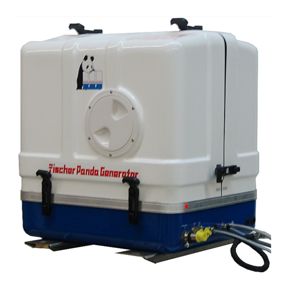
Panda 15000i PMS generator 4. Panda 15000i PMS generator 4.1 Type plate at the generator Fig. 4.1-1: Panda 15000i PMS generator Fig. 4.1-2: Type plate 4.5.16 Kapitel/Chapter 4: Panda 15000i PMS generator - Seite/Page 35... -
Page 36: Description Of The Generator
Ventilation pipe to external expansion tank Sound cover base part Generator housing with coil Raw water injection pipe Charge controller for DC-alternator Exhaust hose Air suction housing Thermosensor Watercooled exhaust elbow Seite/Page 36 - Kaptitel/Chapter 4: Panda 15000i PMS generator 4.5.16... -
Page 37: Left Side View
Impeller filter Fuel solenoid switch Actuator Raw water pump Housing with iControl electronic board (DO NOT OPEN) Suction hose, air suction housing - induction elbow Raw water intake Air suction housing 4.5.16 Kapitel/Chapter 4: Panda 15000i PMS generator - Seite/Page 37... -
Page 38: Front View
22) Thermostat housing with ventilation screw 11) Cable for inverter control 23) Ventilation screw internal cooling water pump 12) Passage for starter battery cable (-) 24) Pulley for internal cooling water pump Seite/Page 38 - Kaptitel/Chapter 4: Panda 15000i PMS generator 4.5.16... -
Page 39: Back View
Panda 15000i PMS generator 4.2.4 Back view Fig. 4.2.4-1: Back view Charge controller for DC-alternator Suction air intake Generator front cover Air suction housing Sound cover base part 4.5.16 Kapitel/Chapter 4: Panda 15000i PMS generator - Seite/Page 39... -
Page 40: View From Above
Oil filler neck with cap Fuel solenoid valve Watercooled exhaust elbow Raw water intake Ventilation pipe to external expansion tank Ventilation screw internal cooling water pump Charge controller for DC-alternator Seite/Page 40 - Kaptitel/Chapter 4: Panda 15000i PMS generator 4.5.16... -
Page 41: Details Of Function Units
Panda 15000i PMS generator 4.3 Details of function units 4.3.1 Remote control panel - See Panda iControl manual 4.3.2 Components of the cooling system (raw- and freshwater) Fig. 4.3.2-1: Cooling system 4.5.16 Kapitel/Chapter 4: Panda 15000i PMS generator - Seite/Page 41... -
Page 42: Components Of The Fuel, Air Intake And Exhaust System
Panda 15000i PMS generator 4.3.3 Components of the fuel, air intake and exhaust system Fig. 4.3.3-1: Fuel, air intake and exhaust system Seite/Page 42 - Kaptitel/Chapter 4: Panda 15000i PMS generator 4.5.16... -
Page 43: Components Of The Electrical System
Panda 15000i PMS generator 4.3.4 Components of the electrical system Fig. 4.3.4-1: Electrical system 4.5.16 Kapitel/Chapter 4: Panda 15000i PMS generator - Seite/Page 43... -
Page 44: Components Of The Lubrication System
Panda 15000i PMS generator 4.3.5 Components of the lubrication system Fig. 4.3.5-1: Lubrication system Seite/Page 44 - Kaptitel/Chapter 4: Panda 15000i PMS generator 4.5.16... -
Page 45: Sensors And Switches For Operating Surveillance
If the impeller pump drops out and deliveres no more raw water, the exhaust connection becomes extremely hot. Thermo-switch coil Fig. 4.3.6-3: Thermo-switch coil One thermo sensor is located in the stator winding 4.5.16 Kapitel/Chapter 4: Panda 15000i PMS generator - Seite/Page 45... -
Page 46: Operation Instructions - See Panda Icontrol Panel Manual
4.4 Operation instructions - See Panda iControl panel manual 4.4.1 Daily routine checks before starting - See Panda iControl manual 4.4.2 Starting generator - See Panda iControl manual 4.4.3 Stopping the generator - See Panda iControl manual Seite/Page 46 - Kaptitel/Chapter 4: Panda 15000i PMS generator 4.5.16... -
Page 47: Installation Instructions
Damages caused by faulty or incorrect installation are not covered by the warranty. 5.1 Personal requirements The described installation must be done by a technical trained person or a Fischer Panda service point. 5.1.1 Hazard notes for the installation see “Safety first!” on Page 12. - Page 48 Installation Instructions tools and special tools. Incorrect or damaged tools can result injuries. Oil and fuel vapours can ignite at contact with ignition Warning!: Danger of fire sources. Therefore: • No open flames during work on the generator. • Do not smoke. •...
-
Page 49: Place Of Installation
Installation Instructions 5.2 Place of installation 5.2.1 Preliminary remark • There must be sufficient fresh air supply for the combustion air. • It has to be ensured that the cooling air supply from underneath or sidewise is sufficient. • During operation the sea cock has to be opened. •... -
Page 50: Advice For Optimal Sound Insulation
5.3 Generator Connections Sample for the connection at the Fischer Panda generator. See the description of the generator for the original loca- tion. All electrical wires are connected within the capsule tightly to the motor and the generator. This is also the case for fuel lines and cooling water lines. -
Page 51: Installation Of The Cooling System - Raw Water
Installation Instructions Fig. 5.3-2: Connection at the Generator - sample 1) External cooling water expansion tank Example - see section 5.2 for detailed information 2) External ventilation valve 5.4 Installation of the cooling system - raw water 5.4.1 General information The genset should have its own raw water (coolant water) inlet and should not be connected to any other engine systems. -
Page 52: Generator Installation Above Waterline
In this case the impeller should be removed out of the impeller pump. Contact Fischer Panda for further information. Never change the impeller for many years, without NOTE: exchanging the old pump. - Page 53 Installation Instructions Fig. 5.4.5-2: Rubber hose for vent valve - example The rubber hose for the external vent valve will be cut..and bend upwards. Fig. 5.4.5-3: Split rubber hose for vent valve Both hose ends will be extended respectively with a hose and connected with a vent valve 600 mm over the waterline.
-
Page 54: Raw Water Installation Scheme
Installation Instructions 5.4.5.1 Raw water installation scheme Fig. 5.4.5.1-1: Raw water installation schema Seite/Page 54 - Kaptitel/Chapter 5: Installation Instructions 4.5.16... -
Page 55: Installation Of The Cooling System - Fresh Water
Installation Instructions 5.5 Installation of the cooling system - fresh water 5.5.1 Position of the external cooling water expansion tank Position of the external cooling water expansion tank Fig. 5.5.1-1: Position of the external cooling water expansion tank The Panda generator is normally supplied with an additional, external cooling water expansion tank. -
Page 56: Installation Of The Water Cooled Exhaust System
Installation Instructions 5.6 Installation of the water cooled exhaust system 5.6.1 Installation of the standard exhaust system The generator exhaust system must remain completely independent and separate from the exhaust system of any other unit(s) on board. The water lock must be installed at the lowest point of the exhaust system. An optional noise insulated water lock can also be installed. -
Page 57: Possible Cause For Water In The Exhaust Hose
Installation Instructions Thereby, the position of the generator and the waterlock, as well as the arrangement of the cooling water and exhaust hoses play the decisive role. If the waterlock is arranged in an unfavourable position, the cooling water flowing back in the exhaust hose can rise so high, that it reaches the exhaust stack. -
Page 58: The Volume Of The Waterlock
Installation Instructions The deeper the waterlock is located underneath the generator, the better the protection from entering water into the combustion chamber. The picture below shows that the distance between the critical point at the exhaust elbow and the maximum permissible water level in the exhaust hose is stated with 600 mm. - Page 59 Installation Instructions center line. See the following pictures: Fig. 5.7.3.1-1: Ideal position of the waterlock In Fig. 5.7.3.1-1, the waterlock is mounted in center underneath the generator. When the ship tilts, the position of the waterlock related to the critical point at the exhaust hose, changes only slightly. Fig.
-
Page 60: Example Of The Installation Of The Waterlock Off-Center And Possible Effects
Installation Instructions Fig. 5.7.3.1-4: Tilted position 45 degrees Tilted position 45 degrees - Fig. 5.7.3.1-4 In this case the water level rise so high, that the distance constitutes only 325 mm. Even when the water lock is mounted in the ideal spot, at an extremely tilted position of 45 degrees there is still the risk that water can get straight into the discharge stack area through strong rocking motions („sloshing“). - Page 61 Installation Instructions Fig. 5.7.3.2-2: Tilted position 45 degrees Tilted position 45 degrees - Fig. 5.7.3.2-2 The water level is now at the same height as the critical point at the exhaust elbow. If the ship is sailed in a tilted position of 45 degrees with an installation like this, the ingress of cooling water into the combustion chamber is inevitable.
-
Page 62: Exhaust / Water Separator
In order to reduce the noise level of the generator unit to a minimum, an optional exhaust outlet muffler can be mounted next to the through-hull fitting. Additionally there is a component at Fischer Panda, which acts as both an „exhaust goose neck“, and water separator. -
Page 63: Fuel System Installation
Installation Instructions The exhaust noise should be almost inaudible. Fig. 5.9.0-1: Example for an unfavourable Installation Example of an unfavourable installation: - Water lock not far enough below the lowest level of the generator - Distance water lock to gooseneck too large 5.10 Fuel system installation Fig. -
Page 64: Connection Of The Fuel Lines At The Tank
Installation Instructions External fine filter Fig. 5.10-2: externer Feinfilter At generators with Kubota EA 300 or Farymann engines, the fine filter is delivered with the generator. This fine filter should be installed in the fuel feed line next to the generator. representative picture 5.10.1 Connection of the fuel lines at the tank General fuel feed and return line must be connected to the... -
Page 65: Generator Dc System Installation
Installation Instructions 5.11 Generator DC system installation The Panda 5000i has no DC alternator to charge the Note: Starter battery. The Starterbattery must be charged by an external device. It is recommended to install an additional starter battery for the generator. The generator is then independent from the remaining battery set. - Page 66 Installation Instructions The batteries must be installed in such a way that they do not chafe through or other mechanical load can be stripped. The battery poles must be secured against unintentional short-circuit. The positive battery cable within the generator must be shifted in such a way that it is protected against heat and vibrations by appropriate sleeve/protective pipe.
- Page 67 Installation Instructions DC Starter Motor Fig. 5.11.1-3: DC Starter Motor All Panda generators are equipped with an independent DC starter motor. 1. Solenoid switch for starter motor 2. Starter motor Fig. 5.11.1-4: Connection starterbattery 12V - schema 1. Generator 3. Fuse 2.
-
Page 68: Connection Of The Remote Control Panel - See Panda Icontrol Panel Manual
Installation Instructions Fig. 5.11.1-5: Connection starterbattery 24V - schema 1. Generator 3. Fuse 2. Battery block 4. Battery main switch 5.11.2 Connection of the remote control panel - See Panda iControl panel manual 5.12 Generator AC system installation Before the electrical system is installed, READ the ATTENTION!: Danger to Life - High voltage SAFETY INSTRUCTIONS of this manual FIRST! Be sure that all electrical installations (including all safety... -
Page 69: Installation Pmgi Inverter - See Separate Pmgi Inverter Manual
Installation Instructions Fig. 5.12.0-1: Electrical installation - example 1. Generator 5. Starter battery DC 2. Electrical fuel pump DC 6. Fuse 3. PMGi inverter 7. Battery switch 4. iControl panel 5.12.1 Installation PMGi inverter - See separate PMGi inverter manual 4.5.16 Kapitel/Chapter 5: Installation Instructions - Seite/Page 69... - Page 70 Installation Instructions Seite/Page 70 - Kaptitel/Chapter 5: Installation Instructions 4.5.16...
-
Page 71: Generator Operation Instruction
Generator operation instruction 6. Generator operation instruction 6.1 Personal requirements Only instructed persons are allowed to run the generator. Instructed Persons has read the manual of the generator and all ancillary components and external equipment. He must be acquaint with the specific risks and safety instructions. -
Page 72: Pre-Heating The Diesel Motor
It is harmless for the generator to deliver full nominal power for 2-3 hours. The hole conception of the Fischer Panda generator make sure, that the full power operation at extreme condition will not increase the engine temperatures over. Please note that the emissions of the generator also increase at full power operation. -
Page 73: Protection Conductor
6.3.5 Operating control system on the Fischer Panda generator Fischer Panda generators are equipped with various sensors/temperatures switches. The combustion engine is further equipped with a oil pressure control switch, which switches the motor off, if the oil pressure sinks to a particu- lar level. -
Page 74: Optional Electromagnetic Clutch
Generator operation instruction 6.6 Optional Electromagnetic Clutch The activation of the electromagnetic clutch will be monitored by the icontrol control unit. The icontrol control unit will raise the generator from variable to top speed. the parallel operation is still active and the load balancing will work in limited range. -
Page 75: Maintenance Instructions
7.1 Personal requirements All maintenance, if not special marked, can be done by the trained persons. Further maintenance must be done by technical personal or Fischer Panda service points. 7.2 Hazard notes for the maintenance and failure Follow the general safety instruction at the front of this Notice!: manual. - Page 76 Maintenance Instructions Contact with engine oil, antifreeze and fuel can result in Danger!: Danger of poisoning damage to health. Therefor: • Avoid skin contact with engine oil, fuel and antifreeze. • Remove oil and fuel splashes and antifreeze from the skin immediately.
-
Page 77: Environmental Protection
Maintenance Instructions 7.3 Environmental protection Danger to the environment due to mishandling! Environmental protection. Significant environmental damage can occur, particularly for incorrect disposal, if environmentally hazardous operating materials are mishandled. Therefore: • Always observe the instructions mentioned below. • Take immediate action if environmentally hazardous materials reach the environment. - Page 78 Oil should be refilled, if the oil-level is under 1/3 between the minimum and the maximum mark. Fischer Panda recommends an oil-level of 2/3 between the minimum and the maximum mark. If the oil-level is under the MIN-mark, check how many operating hours went by since the last oil change, by means of your service manual or an existing oil change tag.
-
Page 79: Refilling Oil
• if the oil-level is under the minimum mark by less than 50h, there might be a technical problem! In that case, we recommend going to a shop or a Fischer Panda service point. • if the oil is cloudy or even „creamy“, coolant might have mixed with the oil. See a garage or a Fischer Panda service point immediately. -
Page 80: Replacement Of Engine Oil And Engine Oil Filter
Maintenance Instructions 7.7 Replacement of engine oil and engine oil filter You require: - Engine oil. See attachment. - New oil filter (not with generators with EA300 engines) - Sealing for oil drain screw - Personal protective gear - Container to collect used oil (heat resistant and of sufficient size) - Open-ended wrench for oil drain screw - Paper towels and cloth... - Page 81 Maintenance Instructions 2. Loosen oil filling cap Fig. 7.7-1: Oil filling cap Unscrew the oil filling cap. This is necessary, because otherwise a vacuum will form and the oil can not completely drain off. Sample picture 3. Open oil drain screw. Fig.
-
Page 82: After The Oil Change
Maintenance Instructions Oil screen with generators with EA300 engines Fig. 7.7-4: Oil screen The oil screen should be cleaned every 500 operating hours: to do so follow the instructions in the engine manual. Use spanner size 17 mm. Sample picture 6. -
Page 83: Verifying The Starter Battery And (If Necessary) The Battery Bank
Maintenance Instructions 7.8 Verifying the starter battery and (if necessary) the battery bank Check the condition of the battery. Proceed here as prescribed by the battery manufacturer. If from the battery manufacturer not otherwise mentioned. 7.8.1 Battery 7.8.1.1 Check battery and cable connections •... -
Page 84: Check Electrolyte Density
Maintenance Instructions 7.8.1.3 Check electrolyte density • Measure the electrolyte density of individual cells with a Fig. 7.8.1.3-1: Battery commercial hydrometer. The hydrometer reading (see table on following page) indicates the battery’s state of charge. During measurement, the temperature of the electrolyte should preferably be 20 °C. - Page 85 Maintenance Instructions 2. Press failure bypass switch and keep firmly pressed. Fig. 7.9-1: Failure bypass switch The electrical fuel pump must be audible. Switching on and off the solenoid valve at the generator will be audible by pressing the failure bypass switch (if capsule removed).
-
Page 86: Replacement Of The Fuel Filter
Maintenance Instructions 7.9.1 Replacement of the fuel filter Exchanging the filter, depending upon fuel contamination, Fig. 7.9.1-1: Fuel Filter should take place after 300 operational hours at the very least. The inlet must be clamped, before exchanging the filter. Remove the hoses from the used filter and fasten them to the new filter. -
Page 87: Checking The Water Separator In The Fuel Supply
Maintenance Instructions 2. Unscrew the filter element from the mount (left hand Fig. 7.9.1.1-3: Fuel filter rotation). 3. Screw the new filter element into the mount. Fig. 7.9.1.1-4: Fuel filter 4. Lubricate the sight glasses o-ring with a heat resistant grease (Specification: Antiseize) and screw the sight glass back into its mount (right hand rotation). -
Page 88: Replacing The V-Belt At Kubota 02/03/05 Series
Maintenance Instructions 7.11 Replacing the V-belt at Kubota 02/03/05 series The described procedure is representative for Fischer Panda NOTE:Reprehensive procedure generators. The original location of the item must be taken from the generator description of this manual. All replacements and repairs should be done by a trained person. -
Page 89: Replace The Air Filter Mat
Maintenance Instructions 5. The V-belt is tensioned by pulling back the alternator. The Fig. 7.11-4: Replacing the V-belt V-belt should yield approx. 1 cm when pushed in with a thumb. Re-tighten the screws above and below the alternator. 7.11.1 Replace the air filter mat 1. -
Page 90: Alternative Replacement Of The Air Filter Mat With Pull Out Holder
Maintenance Instructions 7.11.2 Alternative replacement of the air filter mat with pull out holder 1. Air filter housing with pull out holder. Fig. 7.11.2-1: Air suction housing with pull out holder 2. Tip the two fasteners 90°. Fig. 7.11.2-2: Air suction housing with pull out holder 3. - Page 91 Maintenance Instructions 4. Replace the air filter mat. Fig. 7.11.2-4: Air suction housing with pull out holder 5. Re-assembly in reversed order. 4.5.16 Kapitel/Chapter 7: Maintenance Instructions - Seite/Page 91...
-
Page 92: Alternative Replacement Of The Air Filter At Housing With Snap Fasteners
Maintenance Instructions 7.11.3 Alternative replacement of the air filter at housing with snap fasteners 1. Open the combustion air housing by loosening the closure Fig. 7.11.3-1: Air suction housing on the right side of the housing. 01. Closure 2. Open the combustion air housing by loosening the closure Fig. -
Page 93: First Filling And Ventilation Of The Internal Cooling Water Circuit
Maintenance Instructions 7.11.4 First filling and ventilation of the internal cooling water circuit The expansion tank is supplied with a pressure relief ATTENTION!: Risk of scalding. valve in the cap with 500 mbar. It is possible when operating the generator hot cooling water can leak here if there is an overpressure. -
Page 94: Anti-Freeze In The Cooling Water Circuit
Maintenance Instructions After filling the generator must be started. During this first phase of start-up, the generator may not be loaded. Switch off the generator after approx. 10 seconds of operation! 5. Repeat the steps 1-4 till no more air comes out of the venting screw at the thermostat housing. Close the venting screws. -
Page 95: The Raw Water Circuit
Maintenance Instructions 7.11.6 The Raw water circuit 7.12 The raw water circuit 7.12.1 Clean raw water filter The raw water filter should be released regularly from Fig. 7.12.1-1: Raw water filter arrears. In each case the water cock must be closed before. It is mostly sufficient to beat the filter punnet. - Page 96 Maintenance Instructions pump is particularly critical in coral water bodies. Cases are well-known, which a impeller pump had so strongly run after 100 hours already that the lip seal on the wave was ground in. In these cases sharp crystal parts of the coral sand assess in the rubber seal and affect like an abrasive the high-grade steel shank of the impeller pump.
-
Page 97: Replacement Of The Impeller
Maintenance Instructions 7.13.1 Replacement of the impeller Close the raw water stop cock. Fig. 7.13.1-1: Raw water cock Representative picture Raw water pump on the front side of the genset. Fig. 7.13.1-2: Raw water pump Representative picture Remove the cover of the raw water pump by loosen the Fig. - Page 98 Maintenance Instructions Fig. 7.13.1-4: Impeller pump Pull to the impeller with a multigrip pliers of the wave. Mark the impeller, to make sure that these is used in the correct position at re-installation. Representative picture Check to the impeller for damage and replace it if Fig.
-
Page 99: Generator Failure
Generator Failure 8. Generator Failure 8.1 Personal requirements The work described here, unless otherwise indicated, are performed by the operator. More repair work may be performed only by specially trained personnel or by authorized repair shops (Fischer Panda service points). This is especially for working on the valve timing, fuel injection system and the engine repair. 8.2 Safety instructions for this chapter Also consider the general safety instructions at the first Notice!:... - Page 100 Generator Failure Warning!: Danger of fire Oil and fuel vapours can ignite on contact with ignition sources. Therefore: - No open flames during work on the generator. - Do not smoke. - Remove oil and fuel residues from the generator and floor. Danger!: Danger of poisoning Contact with engine oil, antifreeze and fuel can result in dam- age to health.
-
Page 101: Tools And Measuring Instruments
Generator Failure 8.3 Tools and measuring instruments In order to be able to manage disturbances while driving, following tools and measuring instruments should belong to the equipment on board: • Multimeter for voltage (AC), frequency and resistance • Measuring instrument for inductance •... -
Page 102: Low Generator-Output Voltage
Generator Failure 8.4.1 Low generator-output voltage Before working on the System read the section “Safety ATTENTION! first!” on Page 12. If the produced alternating voltage is too low, switch the load off, in order to relieve the generator. Mostly the problem already solved. -
Page 103: Stop Solenoid
Generator Failure insulated casing, which prevents heat loss. Failure bypass switch Fig. 8.6.2-1: Failure bypass switch This period can be reduced by pushing the button on the front of the generator. The generator can be started by means of the remote control as long as the button is depressed. The switch/button bypasses any faults allowing the generator to run. -
Page 104: Troubleshooting Table
Generator Failure Notice!: When starting the „START“-button may not be pressed longer than 5 sec., because the stop solenoid pulls too much current over the starter. Otherwise the stop solenoid must be disconnected. Stop solenoid (optional) Fig. 8.6.3-1: Stop solenoid 8.7 Troubleshooting table For troubleshooting see section 9.1, “Troubleshooting,”... -
Page 105: Tables
Tables 9. Tables 9.1 Troubleshooting GENERATOR OUTPUT VOLTAGE TOO LOW If the generator delivers less than 24V current („undervoltage“), there can be various reasons for this: Cause Solution PGMi is overloaded. Reduce the electrical load. (Switch off load) Motor is not reaching the rated rpm. Refer to „motor faults“... - Page 106 Tables DROP IN THE SPEED OF THE MOTOR Cause Solution Too much oil. Drain oil. Lack of fuel. Check fuel supply system: - fuel filter, renew if necessary - check fuel pump - check fuel lines (bleed if necessary) Lack of intake air. Check air intake paths.
-
Page 107: Technical Data
Tables 9.2 Technical data 9.2.1 Technical Data Engine 9.3 Technical data Fig. 9.3-1: Technical data igenerators Panda 4800i Panda 5000i Panda 8000i Panda 10000i Panda 15000i Type Faryman 18W430 EA300 Z482 Z602 D902 Governor iControl2 iControl2 iControl2 iControl2 iControl2 Automatic start booster Cylinder Bore 82 mm... -
Page 108: Diameter Of Conduits
Tables Panda 25i Panda 45i Rated speed 1500 rpm 2700 rpm Idle running speed 1800 rpm 1600 rpm Valve clearance (engine cold) 0,2 mm 0,18 - 0,22 mm Cylinder head nut torque 68 Nm 93,1 - 98 Nm Compression ratio 22:1 Lubrication oil capacity 6,0 l... -
Page 109: Cable Cross Section
Tables Generator type Ø Cooling water conduit Ø Exhaust conduit Ø Fuel conduit [mm] Freshwater Seawater Supply Return [mm] [mm] [mm] [mm] Panda PMS 50 MB Panda PMS 60 MB Panda PMS 75 MB Panda PMS-HD 7,5-4 KU Panda PMS-HD 09-4 KU Panda PMS-HD 12-4 KU Panda PMS-HD 17-4 KU Panda PMS-HD 22-4 KU... -
Page 110: Coolant Specifications
Use a mixture of water and antifreeze. The antifreeze needs to be suitable for aluminium. The antifreeze concentration must be regularly checked in the interests of safety. Fischer Panda recommend to use the product: GLYSANTIN PROTECT PLUS/G 48 Engine coolant automotive industry Product description Product name GLYSANTIN ®... -
Page 111: Coolant Mixture Ratio
Tables Chemical and physical properties Reserve alkalinity of 10ml ASTM D 1121 13 – 15 ml HCl 01 mol/l Density, 20 °C DIN 51 757 procedure 4 1,121 – 1,123 g/cm Water content DIN 51 777 part 1 max. 3,5 % pH-value undiluted 7,1 –... - Page 112 Tables Seite/Page 112 - Kaptitel/Chapter 9: Tables 4.5.16...
-
Page 113: Inverter Panda Pmgi
Inverter Panda PMGi 10. Inverter Panda PMGi Document Hardware Software Actual: Replace: PMGi - representative picture PMGi 25 4.5.16 Kapitel/Chapter 10: Inverter Panda PMGi - Seite/Page 113... -
Page 114: Safety Instruction
Inverter Panda PMGi 10.1 Safety instruction The PMGi may not be taken into use with the cover removed. All servicing-, maintenance or repair work may only be carried out, when the generator motor is not running. Electrical voltages above 60 volts are always dangerous Electrical power: DANGER TO LIVE! to life. -
Page 115: Front Side/Connection Side Pmgi 230 V - Representative Picture
Inverter Panda PMGi 10.3 Front side/connection side PMGi 230 V - representative picture To connect the PMGi use the prepared cable and connect to Fig. 10.3-1: Connection side socket 7 (PMGi in) Connect your termination box with the socket 1. Do not cover the air out grille (4) 1. -
Page 116: Alternative Front Side/Connection Side Pmgi 120 V/240 V - Representative Picture
Inverter Panda PMGi 10.5 Alternative front side/connection side PMGi 120 V/240 V - representative picture To connect the PMGi use the prepared cable and connect to Fig. 10.5-1: Connection side socket 4(PMGi in) Connect your termination box with the socket 1. Do not cover the air out grille (3) 1. -
Page 117: Pmgi Input
Inverter Panda PMGi Three phase - PMGi AC out Fig. 10.5-2: PMGi AC out Connect your AC terminal box here representative picture single phase - PMGi AC out with internal PE/N bridge. Fig. 10.5-3: PMGi AC out At PMGi where the PE/N jumper is missing next to the PGMGI out, a internal PE/N bridge is installed (f.e. -
Page 118: Control
Inverter Panda PMGi PMGi input alternative Version Fig. 10.5.1.2-2: PMGi input Connect the generator power out cable here. representative picture 10.5.1.3 Control Connect the control cable from the generator here Fig. 10.5.1.3-1: Control representative picture 10.5.1.4 External PE/N Bridge The PE/N Bridge can be installed here for RCD or Fig. -
Page 119: Back Side - Top Side
Inverter Panda PMGi 10.6 Back side - Top side Inside of the PMGi a fan is mounted. The air holes and air Fig. 10.6.0-1: Back side grille should not be covered. 01. Air holes/Air grille - Do not cover Inside of the PMGi are up to 550 VAC. The cover of the Attention! PMGi should only be opened by special trained persons! Danger for Live! -
Page 120: Settings For The Use Of Igenerators With Power Inverter
Inverter Panda PMGi 10.7 Settings for the use of iGenerators with power inverter For the use of power inverter with the PMGi, the settings of ATTENTION: Wrong settings can destroy the the power inverter must be modified. PMGi Wrong settings can damage or destroy the PMGi. The settings for the Victron power inverter must be adapted for the power inverters of other brands. -
Page 121: Settings In The Victron Ve Configure Ii Software - Inverter
Inverter Panda PMGi 10.7.2 Settings in the Victron VE Configure II Software - Inverter Fig. 10.7.2-1: Settings in the Victron VE configure II Software 10.7.2.1 Assist current boost factor To reduce the action of the power inverter on the iGenerator, the Assist current boost factor must be reduced from 2.0 to1.3. -
Page 122: Operation Manual
Inverter Panda PMGi 10.8 Operation manual 10.8.1 Primary remarks / Winter operation The PMGi can operate in the range of -20 °C to +40 °C. 10.8.2 Load at the PMGi Do not overload the PMGi. It will go on error. 10.8.3 Automatic start The generator can start (depending on the remote control panel) by an external signal (automatic start) If you use this option make sure that the load is connected to the PMGi after the output has reached the nominal... -
Page 123: Installation Of The Pmgi
Inverter Panda PMGi 10.11Installation of the PMGi The PMGi must be mounted vertical, with the electrical connection down. So you can read the writing on the PMGi. The surface where the PMGi is mounted should be smoothed and support the heat transfer. The Air holes and Air grille must be not covered and enough cooling air must be pleasant at any time for the PMGi. -
Page 124: 2Cooling Water Scheme If The Radiator Is Higher Than The Generator /Inverter
Inverter Panda PMGi 10.11.1.2 Cooling water scheme if the Radiator is higher than the Generator /Inverter Fig. 10.11.1.2-1: Cooling water scheme if the Radiator is higher than the Generator /Inverter 10.11.1.3 Cooling water scheme if the Radiator is on the same level or lower than the Generator /Inverter Fig. -
Page 125: 4Cooling Water Scheme For Pvk-Uk Igenerators
Inverter Panda PMGi Fig. 10.11.1-2: Cooling water scheme if the Radiator is on the same level or lower than the Generator /Inverter 10.11.1.4 Cooling water scheme for PVK-UK iGenerators Fig. 10.11.1.4-1: Cooling water scheme for PVK-UK iGenerators 4.5.16 Kapitel/Chapter 10: Inverter Panda PMGi - Seite/Page 125... -
Page 126: 5Cooling Water Connection Schema - Marine (Pms) Generator
Inverter Panda PMGi 10.11.1.5 Cooling water connection schema - Marine (PMS) Generator Fig. 10.11.1.5-1: Cooling water connection schema - Marine (PMS) Generator Seite/Page 126 - Kaptitel/Chapter 10: Inverter Panda PMGi 4.5.16... -
Page 127: Electrical Connection
Inverter Panda PMGi 10.11.2 Electrical connection. Only special trained persons are allowed to make the electrical connection. When an extension cable is required, be sure to use a though rubber sheeted flexible and fireproof cable. Limit length of extension cables depends on the voltage drop along the cable. This drop must be less than 2,5% value of the nominal output voltage. -
Page 128: 3Connection To A System With Isolation Control At Pmgi With Pen Jumper
Inverter Panda PMGi 10.11.2.3 Connection to a system with isolation control at PMGi with PEN jumper For the use of the PMGi with an isolation controlled grid, the external PE-N Bridge must be disconnected. PEN jumper open. 10.11.2.4 Connection to a system with isolation control at PMGi without PEN jumper For the use of the PMGi with an isolation controlled grid, the internal PE-N Bridge must be disconnected. -
Page 129: Pmgi Out
Inverter Panda PMGi 10.12.3 PMGi out Fig. 10.12.3-1: Technische Daten PMGit / Technical data PMGi / PMGi Out PMGi 4000 230 V PMGi 5000 230 V PMGi 5000 120 V Nominale 230 V VAC +/- 5 % ohne 230 V VAC +/- 5 % ohne 120 V VAC +/- 5 % ohne Ausgangsspannung Last / without Load / sans... - Page 130 Inverter Panda PMGi Fig. 10.12.3-2: Technische Daten PMGi / Technical data PMGi / PMGi Out PMGi 8000 230 V PMGi 8000 120 V PMGi 10000 230 V Nominale 230 V VAC +/- 5 % ohne 120 V VAC +/- 5 % ohne 230 V VAC +/- 5 % ohne Ausgangsspannung Last / without Load / sans...
- Page 131 Inverter Panda PMGi Fig. 10.12.3-3: Technische Daten PMGi / Technical data PMGi / PMGi Out PMGi 10000 120 V Nominale 120 V VAC +/- 5 % ohne Ausgangsspannung Last / without Load / sans charge Nominal Voltage Regelung Regulation Stabilität (Kurzzeit (30sec)) Stability (short term (30sec)) Stabilität (Langzeit (4h)) Stability (Long term (4h))
- Page 132 Inverter Panda PMGi Fig. 10.12.3-4: Technische Daten PMGi / Technical data PMGi / PMGi Out PMGi 15000 400 V PMGi 15000 230 V PMGi 15000 120 V Nominale 400 V VAC +/- 5 % ohne 230 V VAC +/- 5 % ohne 120 V VAC +/- 5 % ohne Ausgangsspannung Last / without Load / sans...
- Page 133 Inverter Panda PMGi Fig. 10.12.3-5: Technische Daten PMGi / Technical data PMGi / PMGi Out PMGi 25 230 V PMGi 25 400 V PMGi 25 2x120 V/240 V Nominale 230 V VAC +/- 5 % ohne 400 V VAC +/- 5 % ohne 2x120 V/240 V VAC +/- Ausgangsspannung Last / without Load / sans...
- Page 134 Inverter Panda PMGi Fig. 10.12.3-6: Technische Daten PMGi / Technical data PMGi / PMGi Out PMGi 45 230 V PMGi 45 400 V PMGi 60 400 V Nominale 230 V VAC +/- 5 % ohne 400 V VAC +/- 5 % ohne 400 V VAC +/- 5 % ohne Ausgangsspannung Last / without Load / sans...
-
Page 135: Pmgi Protections
Inverter Panda PMGi Fig. 10.12.3-7: Overload Art of output Max. current Comment 230 VAC 87 A +/- 0.5 A after the overload protection was activated, the generator must be switched off and all load must be disconnected. 10.13PMGi protections 10.13.1 Short circuit To operate the short circuit protection a fuse must be put in series with the live wire. - Page 136 Inverter Panda PMGi Leere Seite / Intentionally blank Seite/Page 136 - Kaptitel/Chapter 10: Inverter Panda PMGi 4.5.16...
-
Page 137: Panda Icontrol2
Panda iControl2 Operating Manual Open-loop and closed-loop control system for Fischer Panda generators Panda iControl2_eng.R08 4.5.16... -
Page 138: Current Revision Status
Reproduction and modification of the manual is permitted only after agreement with the manufacturer! Fischer Panda GmbH, 33104 Paderborn, reserves all rights regarding text and graphics in this document. Details are given to the best of our knowledge. No liability is accepted for correctness. Please note: technical modifications aimed at improving the product may be implemented without prior notice. -
Page 139: Safety Instructions For The Panda Icontrol2
NOTE: Fischer Panda genset manual. If these instructions are not on hand, they can be requested from Fischer Panda GmbH, 33104 Paderborn, Germany. An external signal may trigger an automatic start-up. WARNING: Automatic start-up The generator must not be operated with the cover WARNING: removed. - Page 140 Safety instructions for the Panda iControl2 The flooding valve must be closed. (For PMS version only.) Also observe the safety instructions for the other NOTE: components of your system. Seite/Page 140 - Kaptitel/Chapter 11: Safety instructions for the Panda iControl2 4.5.16...
-
Page 141: General Operation
General operation 12. General operation 12.1 The Panda iControl2 panel The "Panda iControl2 panel" control panel is the control and display unit for the Panda iControl2 control system and represents the interface between the user and the Panda iControl2 controller. The integrated display serves to present the most important data of the system as well as warnings and error messages. -
Page 142: Starting Preparation / Checks (Daily)
General operation 12.2 Starting preparation / Checks (daily) 12.2.1 Marine version 1. Oil level control (ideal level: 2/3 MAX). The level should be about 2/3 of the maximum level of a cold engine. Further, if installed, the oil level of the oil-cooled bearing must be controlled before each start - see sediment bowl at generator front cover!. -
Page 143: Operation
General operation 12.3 Operation 12.3.1 Switching the controller on and off The Panda iControl2 controller is switched on and off with the On/Off button on the Panda iControl2 panel. Press and hold the On/Off button until the start screen with the panda bear appears on the display. The controller is switched off by actuating the On/Off button once more. -
Page 144: Operating Modes
General operation • Oil pressure status • Cylinder head temperature • Temperature of exhaust manifold • Winding temperature • Speed/RPM • Utilisation in percent Fig. 12.3.2-1: Default display screen The Display shows the iControl board input voltage. Note: At generator systems with 12 V starter system these is equal with the starter battery voltage. -
Page 145: Start-Up Mode
General operation Fig. 12.3.3.1-1: Service information screen The total operating hours of the generator are given on the default display screen and on the service information screen. By actuating the cursor-up and cursor-down button in stand-by mode, the service screen can be accessed. This screen is marked with a screwdriver/spanner symbol. -
Page 146: Override Mode
General operation The controller will only perform one starting attempt. If Note: the generator could not be started, the text output "STARTING FAILS" informs you of the failure of the generator starting attempt. Acknowledging the message with the cursor-up, cursor-down, or the Start/Stop button on the Panda iControl2 panel will return the system to stand-by mode. - Page 147 General operation Display screen for single phase generators With the single phase i-series generators, there is an Fig. 12.3.3.4-2: Inverter screen in operation mode additional screen in operation mode for the inverter data. This screen provides the current inverter output voltage and the inverter temperature.
-
Page 148: Panda I-Generator With Electro-Magnet Clutch (Optional)
General operation This screen provides the latest inverter output voltage of the Fig. 12.3.3.4-7: Phase voltage L3 single phases with the matching conductor current and the circuit board temperature. The inverter will be switched off at a circuit board temperature of 75 °C. You can access the inverter screen by actuating the cursor-up button while in operation mode. -
Page 149: Stop Mode
After the delay time, the generator will be stopped automatically. You can interrupt the delay time by pressing the start/stop button. (Not recommend by Fischer Panda. The Engine may overheat) Fig. 12.3.3.6-1: Delay time... - Page 150 General operation The autostart function will remain active even after the Warning!: Automatic start-up controller is switched off and on again with the On/Off button. To deactivate the autostart function, the flag in the EEPROM must be reset with "Disable". Siehe “Activating/deactivating the autostart function ("Autostart")”...
-
Page 151: Other Operating Functions
Dimtime (dimming time) Time until the display switches to dimmed mode, 0-225s, 0= function deactivated Config Password protected area for Fischer Panda associates and Fischer Panda service points Network ID Settings for the network ID of the panel Save & Exit... -
Page 152: Setting The Brightness Of The Backlight ("Backlight" And "Dimtime")
General operation 12.4.2 Setting the brightness of the backlight ("backlight" and "dimtime") The brightness of the display backlight of the Panda iControl2 panel can be varied in ten increments (0-9). Also, the display can be dimmed with a timer if no button is actuated on the control panel for a parameter is able period. To adjust the default brightness and the dimmed brightness, the set-up menu offers the items "backlight 1"... -
Page 153: The Configuration Menu ("Config")
Settings in this area must only be entered by Fischer STOP! Panda associates and Fischer Panda service points. The "config" sub-menu is a password protected area in which the generator type can be selected, and generator parameters in the EEPROM can be modified. - Page 154 General operation To activate the autostart function, select the item Fig. 12.4.6-1: Set-up menu "Autostart" in the set-up menu using the cursor buttons and confirm the selection with the Start/Stop button. In the "Autostart" sub-menu, you can select between the Fig.
-
Page 155: Resetting The Service Interval ("Service")
General operation Then, the controller is shut down. Fig. 12.4.6-6: Goodbye screen prior to shutting down After switching the controller back on, the display status Fig. 12.4.6-7: Default display screen in autostart mode field reading "AUTOSTART" indicates that the autostart function is active, or, if it reads "STANDBY", this means that the autostart function was deactivated: The autostart function will remain active even after the... -
Page 156: Priming The Fuel System ("Prime Fuel")
General operation Resetting the time until the next service Fig. 12.4.7-1: Resetting the time until the next service By actuating the Start/Stop button again, you can reset the service interval to the original interval. The service interval for each generator type is stored in the software. The controller is switched off after resetting the service interval. - Page 157 General operation The Panel shows „Emergency Stop“. Damit wird auch die Spannungsversorgung für den Inverter ausgeschaltet. Das Panel zeigt nach der Betätigung „EMERGENCY STOP!“. The message disappear as soon as the emergency switch is released. Fig. 12.5-1: Not Stop bridge in the cable harness Fig.
- Page 158 General operation Leere Seite / Intentionally blank Seite/Page 158 Kapitel/Chapter 12: General operation 4.5.16...
-
Page 159: Installation
WARNING: Properly dimension your system. designed and adequate for „standard“ installation situations. As Fischer Panda does not know the specific installation and operating situation (e.g. special vehicle shapes, high travel speeds, and special application conditions, etc. ), this installation specification can only serve as a guideline and example. -
Page 160: Disposal Of The Components
Installation only an electrician may carry out the installation of the electrical connections of the generator. Generator and cooling water may be hot during and after WARNING: Hot surface/material operation. Burn/scalding hazard! During operation, overpressure may build up in the cooling system. -
Page 161: Panda Icontrol2 Panel With Installation Housing
Autostart USTART/STOPP Autostart A jumper between terminal 6 and 7 closes the autostart contact. A jumper between terminal 6 and 7 closes the autostart contact. Use only original Fischer Panda connecting cables. Note: 4.5.16 Kapitel/Chapter 13: Installation - Seite/Page 161... -
Page 162: Dimensions
Installation 13.3 Dimensions Fig. 13.3-1: Housing of the Panda iControl2 panel Seite/Page 162 - Kaptitel/Chapter 13: Installation 4.5.16... -
Page 163: Wiring Of The Panda Icontrol2 Controller
The Panda iControl2 controller is connected to the wire harness with the 18-pin jack. The centre 6-pin jack is designed for the Fischer Panda standard bus. The Panda iControl2 panel is connected to this jack. The Fischer Panda CAN bus is connected to the 6-pin jack at the bottom right of the circuit board. The configuration of the connectors is given in the subsequent tables. -
Page 164: Terminal Assignments On The Panda Icontrol2 Controller
Terminal Terminal description Function UBUS Bus supply voltage Fischer Panda bus ground, ground connection between Panda iControl2 controller and Panda iControl2 panel REIZ Exciter line, is switched to ground by the panel if the controller is to switch on DATA+... -
Page 165: Master And Slave Panels
Installation 13.5 Master and Slave Panels With the iControl2 it is possible to have up to four remote control panels at one iGenerator. (One Master + three Slave) The standard iControl panel has the Art. No. 21.02.02.131P. This Panel has integrated termination resistors and is the Master Panel. - Page 166 Installation The original start-up log of the generator must be sent to Note: Fischer Panda to obtain the full warranty. Make sure that you retain a copy for your records. The corresponding forms are included in the generator manual. Seite/Page 166 - Kaptitel/Chapter 13: Installation...
-
Page 167: Maintenance
Maintenance 14. Maintenance 14.1 Maintenance of the iControl2 controller The iControl2 controller is maintenance-free. The fuses of the controller are self-healing. 14.1.1 Cleaning the iControl2 controller The housing shall be cleaned within the scope of the overall generator cleaning. The housing can be wiped off with a soft, lightly dampened cloth. - Page 168 Maintenance Leere Seite / Intentionally blank Seite/Page 168 Kapitel/Chapter 14: Maintenance 4.5.16...
-
Page 169: Warnings And Error Messages
Warnings and error messages 15. Warnings and error messages To enable the safe operation of the generator, the Panda iControl2 controller is programmed with a series of warnings and error messages that influence the generator operation. 15.1 Warnings Warnings are issued when the variable being monitored, e.g. temperature, reaches a defined warning threshold. The warnings are issued on the Panda iControl2 panel display via the cyclical display of the word „HIGH“... -
Page 170: Warning Messages
Warnings and error messages 15.1.2 Warning messages All warning messages defined for the Panda iControl 2 and the corresponding display output are compiled in the subsequent table. Fig. 15.1.2-1: Warning messages Warning message on the display Meaning of warning message „HIGH“... -
Page 171: Error Messages
Cylinder head temperature too high FAULT: WINDING Winding temperature too high FAULT: EXHAUST Exhaust manifold temperature too high NO CONNECTION BUS ERROR Communication error on Fischer Panda bus STARTING FAILS Generator start has failed PROBLEM WITH FUEL SUPPLY! Fuel supply not suitable FAULT: OILPRESS... -
Page 172: Bus Errors
15.0 V 15.2.3 Bus errors If the communication connection is lost on the Fischer Panda bus, an error is output on the display after a period of 10 seconds: This error will occur if at least one of the two data lines Fig. -
Page 173: How To Get To The Error Memory Of The Icontrol2 Panel
Warnings and error messages 15.3.1 How to get to the error memory of the iControl2 Panel? The error memory is easily accessible via the setup menu of the control panel which is open to every user. The setup menu can be accessed as usual: •... -
Page 174: Is It Possible To Upgrade An Old Igenerator Model By The Error Memory
Warnings and error messages 15.3.7 Is it possible to upgrade an old iGenerator model by the error memory? Yes, if the software of the control board and the panel is updated, it is possible to upgrade an existing system by this function. -
Page 175: Annex
Annex 16. Annex 16.1 Technical data 16.1.1 Technical data for iControl2 control unit Fig. 16.1.1-1: Technical data for iControl 2 control unit iControl 2 control unit Supply voltage 12V-13.5V (12V automotive) Current consumption, nominal 175 mA Current consumption, stand-by 2.5 mA Operating temperature -20°C to +85°C Storage temperature... - Page 176 Annex Leere Seite / Intentionally blank Seite/Page 176 Kapitel/Chapter 16: Annex 4.5.16...
Need help?
Do you have a question about the 15000i PMS and is the answer not in the manual?
Questions and answers