Aiphone IXG Series Installation Manual
Guard station, video entrance station, back box for entrance station, lift control adaptor, gateway adaptor.
Hide thumbs
Also See for IXG Series:
- Quick start manual ,
- Operation manual (40 pages) ,
- Quick start programming manual (25 pages)
Table of Contents
Advertisement
Installation Manual
IXG Series
IXG-MK Guard Station
IXG-DM7, IXG-DM7-HID Video Entrance Station
IXG-DM7-BOX Back Box for Entrance Station
IXGW-LC Lift Control Adaptor
IXGW-GW Gateway Adaptor
Introduction
• Read this manual before installation and connection. Read the "Setting Manual" and "Operation Manual". The manuals
can be downloaded from our homepage at "https://www.aiphone.net/support/software-document/".
• After completing installation and connection, program the system according to the "Setting Manual". The system cannot
operate unless it is programmed.
• After performing installation, review with the customer how to operate system.
• Perform installation and connection only after gaining sufficient understanding of the system and this manual.
• The illustrations used in this manual may differ from the actual product.
Advertisement
Table of Contents

Related Manuals for Aiphone IXG Series


Summary of Contents for Aiphone IXG Series
- Page 1 • Read this manual before installation and connection. Read the "Setting Manual" and "Operation Manual". The manuals can be downloaded from our homepage at “https://www.aiphone.net/support/software-document/”. • After completing installation and connection, program the system according to the "Setting Manual". The system cannot operate unless it is programmed.
-
Page 2: Literature Information
Literature information The important information concerning correct operation and what you should observe is marked with the following symbols. Indicates that users may require caution (including warning / caution). Alerts users to prohibited actions. Restricts user actions / provides instructions. Tips and additional information for operation. - Page 3 Notice • If the station is used in areas where there are business-use wireless devices such as a transceiver or mobile phones, it may cause malfunction. • If the station is installed in an area with an extremely strong electrical field, such as in the vicinity of a broadcasting station, it may create interference and cause malfunction.
-
Page 4: Table Of Contents
Table of contents Literature information ...................1 Precautions ....................1 Example of System Configuration..............5 Example of Standard System ..................5 Example of Multi-building System ................6 Part Names and Accessories...............7 IXG-MK ......................... 7 IXG-DM7, IXG-DM7-HID ....................8 IXG-DM7-BOX ......................9 IXGW-LC ........................9 IXGW-GW ........................ - Page 5 Connection Precautions ..................... 20 Cat-5e/6 cable ..........................20 Precautions regarding low-voltage line ..................20 Connection and disconnection of low-voltage lines ..............20 Wiring Connection..................22 IXG-MK ........................22 IXG-DM7, IXG-DM7-HID .................... 23 IXGW-LC ........................24 IXGW-GW ........................24 Specifications .....................25 IXG-DM7-BOX ......................25 IXGW-LC ........................
-
Page 6: Example Of System Configuration
Example of System Configuration ■ Example of Standard System A maximum of 9,999 of the following stations and adaptors can be connected: ※1 ※2 IXG-2C7(-L), IXG-DM7(-HID), IXG-MK, IX-MV7-*, IXGW-LC, IXGW-GW, IX-RS-* , door stations (IX-DA , IX- ※2 ※1 , IX-DV, IX-DVF(-*), IX-SS-2G , IX-SSA(-*), IX-EA) A maximum of 9,999 mobile devices can be connected: ASP-IXGI, ASP-IXGA... -
Page 7: Example Of Multi-Building System
■ Example of Multi-building System Maximum number of buildings: 99 buildings A maximum of 9,999 of the following stations and adaptors can be connected with a multi-building system: ※1 IXG-2C7(-L), IXG-DM7(-HID), IXG-MK, IX-MV7-*, IXGW-LC, IXGW-GW, IX-RS-* , door stations (IX-DV, IX-DVF(-*), ※1 IX-SS-2G , IX-SSA(-*), IX-EA) -
Page 8: Part Names And Accessories
Part Names and Accessories ■ IXG-MK Scheduled for release in the 3rd quarter of 2020. Back view Side view Front view Camera privacy cover lever (on top) Camera angle Status indicator Camera adjustment lever (Orange/Blue) MAC address Handset ※ Reset button microSD ※... -
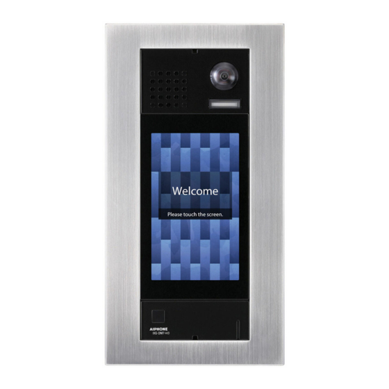
Page 9: Ixg-Dm7, Ixg-Dm7-Hid
■ IXG-DM7, IXG-DM7-HID Front view Back view Special screw MAC address Camera LED for night ※1※2 Terminal cover illumination Under the Terminal cover Speaker micro SD card indicator Touchscreen Connectors (Red) Sensor Card reader LAN (PoE) (IXG-DM7- port ※3 HID only) SW1 Reset button Card reader indicator (Red/Green) (IXG-DM7-HID only) -
Page 10: Ixg-Dm7-Box
■ IXG-DM7-BOX Front view ■ IXGW-LC Front view Low-voltage connection terminal Reset button Lock release lever (Back) Status indicator (Orange) LAN (PoE) port Status indicator (Green) The MAC address is on the back of the device. Included accessories Download guide x 1 Chinese RoHS declaration x 1 - 9 -... -
Page 11: Ixgw-Gw
■ IXGW-GW Front view Not used. Do not open. LAN (PoE) port Reset button Not used Lock release lever (Back) Not used Status indicator (Orange/Green) The MAC address is on the back of the device. Included accessories Product warranty x 1 Download guide x 1 Chinese RoHS declaration x 1 DIN rail x 1 (for Japanese market) -
Page 12: Status Indicator
Status Indicator Refer to "Operation Manual" for additional indicators not listed. ■ IXG-MK :Lit : Off Status (pattern) Description Orange flashing Booting 0.75 sec 0.75 sec Communication failure 0.5 sec 4 sec Firmware version updating 0.25 0.25 0.25 0.25 0.25 Initializing 0.25 0.25... -
Page 13: About Microsd Card
• A maximum of 999 video/audio files can be saved. However, this may vary depending on the size of the video/audio files and the capacity of the microSD card. • Aiphone is not to be held responsible in any way for microSD cards. - 12 -... -
Page 14: How To Install
How to Install ■ IXG-MK ● Mounting the station on a wall Back wiring 3-gang box Attach the station to the mounting bracket. Low-voltage lines Attach the Cat-5e/6 cable handset. Recommended Mounting Low-voltage height (center of gang lines Mounting bracket box) 1,500mm (4' 11'') (attached to the back of the station) -
Page 15: Mounting The Station On The Desktop Stand
● Mounting the station on the desktop stand Attach the mounting bracket to Attach the station to the Attach the the desktop stand. mounting bracket. handset. Cat-5e/6 cable Assemble the desktop ① Insert the stand. connector ※ ※ Position the desktop stand on a into the flat surface for stability. -
Page 16: Ixg-Dm7, Ixg-Dm7-Hid
■ IXG-DM7, IXG-DM7-HID Back Box for Entrance Station (IXG-DM7-BOX) is sold separately. The illustrations explain installation using the IXG-DM7 model. • When installing the station on a rough surface, please seal the station edges to prevent water entering the station. If the station edges are left unsealed on a rough surface, IP65 ingress protection rating is not guaranteed. -
Page 17: Ixgw-Lc
■ IXGW-LC ● Mounting the adaptor directly to a wall 191.5mm (7-9/16”) Position the adaptor with "UP " facing up, and attach the adaptor to the wall. 80mm (3-1/8'') Wall-mounting wood or less screws × 2 (not included) Wire mold Use a covering duct for Cat-5e/6 cable and low-voltage lines, and leave a Screw shaft: φ4.1 or less... -
Page 18: Ixgw-Gw
■ IXGW-GW Pull the lock release lever down to Position the adaptor with "UP " facing up, remove the DIN rail from the adaptor. and mount the adaptor on the DIN rail and then click the adaptor into place. DIN rail Lock release lever DIN rail Attach the DIN rail to the... -
Page 19: Camera View Range And Mounting Position
Camera View Range and Mounting Position ■ IXG-MK ● Camera View adjustment Using the camera angle adjustment lever, the camera can be tilted down (0° to -20°). Please adjust the camera to the optimal position. Back view Camera angle adjustment lever -20°... -
Page 20: Ixg-Dm7, Ixg-Dm7-Hid
■ IXG-DM7, IXG-DM7-HID ● Mounting positions and image view area • Follow the applicable laws and regulations for mounting location. Wide view Wide view Vertical Mounting position 1,300 mm (4' 3") Mounting position 1,500 mm (4' 11") 2,050 mm (6' 8") 1,850 mm (6' 0") 1,150 mm (3' 9") 1,150 mm (3' 9") -
Page 21: How To Connect
How to Connect ■ Connection Precautions ● Cat-5e/6 cable • For connection between devices, use a straight-through cable. • If necessary, when bending the cable, please observe the manufacturer's recommendations. Failure to do so could cause a communication failure. • Do not strip away the cable insulation any more than is necessary. •... - Page 22 • If the connector-attached lead wire is too short, extend the lead with an intermediate connection. • As the connector has polarity, perform the connection correctly. If the polarity is incorrect, the device will not operate. • When using the crimp sleeve method, if the end of the connector-attached lead wire has been soldered, first cut off the soldered part and then perform crimp.
-
Page 23: Wiring Connection
Wiring Connection ■ IXG-MK • Insulate and secure unused low-voltage lines and the connector-attached lead wire. Guard Station ※ IEEE802.3 af IXG-MK Cat-5e/6 straight Brown PE0.65 - 1.2(17 - 22AWG)-2C PoE Switch ※ LAN/PoE ※1 Contact Input 1 100m (330') Orange PE0.65 - 1.2(17 - 22AWG)-2C ※1... -
Page 24: Ixg-Dm7, Ixg-Dm7-Hid
■ IXG-DM7, IXG-DM7-HID • Insulate and secure unused low-voltage lines and the connector-attached lead wire. Video Entrance Station IXG-DM7 (-HID) IEEE802.3 af Brown LAN(PoE) Cat-5e/6 straight ※1 Contact Input 1 PoE switch 100m (330') ※1 Contact Input 2 Orange ※1 Contact Input 3 Brown Yellow... -
Page 25: Ixgw-Lc
※4 Card Reader Specifications Power requirement 10.80 - 14.50 VDC at 250mA Interface Wiegand ※5 Compatibility access controller • HoneyWell NetAXS-123 For the compatibility card, see “IXG-DM7, IXG-DM7-HID (→page 8)”. ■ IXGW-LC Lift Control Adaptor IXGW-LC IEEE802.3 af LAN(PoE) Cat-5e/6 straight PoE switch 100m(330') PE0.65-1.2 (17-22AWG)-2C... -
Page 26: Specifications
Specifications Refer to "Operation Manual" for IXG-MK, IXG-DM7, IXG-DM7-HID. ■ IXG-DM7-BOX Mounting Flush wall-mounted Materials SPCC t1.6 Dimensions 156 mm (6-1/8") [W] × 317 mm (12-1/2") [H] × 60 mm (2-3/8") [D] Mass Approx. 1.8 kg (4.0 lbs) ■ IXGW-LC Power PoE (IEEE802.3af Class 0 standard) Current consumption... -
Page 27: About The Error Screen
About the Error Screen If the error screen appeared on the entrance screen, follow the steps below: • Confirm unit has been set up correctly using the IXG Support Tool. • Check network connection using IXG Supervision Tool. • Check wiring to Unit. - 26 -... - Page 28 AIPHONE CO., LTD., NAGOYA, JAPAN Ⓑ Issue Date Mar. 2020 FK2526 P0320 RQ 62253...
Need help?
Do you have a question about the IXG Series and is the answer not in the manual?
Questions and answers