
Related Manuals for HP 64780A


Summary of Contents for HP 64780A
- Page 1 Installation/Service/Terminal Interface Guide MC68360 Emulator/Analyzer (HP 64780A)
- Page 2 Notice Hewlett-Packard makes no warranty of any kind with regard to this material, including, but not limited to, the implied warranties of merchantability and fitness for a particular purpose. Hewlett-Packard shall not be liable for errors contained herein or for incidental or consequential damages in connection with the furnishing, performance, or use of this material.
- Page 3 Printing History New editions are complete revisions of the manual. Many product updates and fixes do not require manual changes, and manual corrections may be done without accompanying product changes. Therefore, do not expect a one-to-one correspondence between product updates and manual revisions. Edition 1 64780-97000, December 1993 Edition 2...
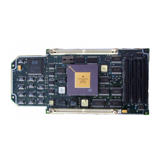
- Page 5 5V and 3.3V operation. The emulator plugs directly into a PGA socket, and it can be plugged into a PQFP target system using optional accessories. In this manual, the emulator is referred to by Model Number 64780A, and the Motorola microprocessor is referred to by MC68360.
- Page 6 Motorola continues to ship prior revisions of the MC68360, and the MC68MH360. If you would like to use one of the non-Revision C parts in your HP 64780A emulator, HP offers an upgrade kit. Contact your local HP field engineer for ordering information.
- Page 7 Emulation-bus analyzer • 80-channel emulation-bus analyzer • Post-processed dequeued trace with symbols • Eight events, each consisting of address, status, and data comparators • Events may be sequenced eight levels deep and can be used for complex trigger qualification and selective store Emulation memory •...
- Page 8 HP 64700 Card Cage Installation/Service Guide, tells you more about installation and configuration of the HP 64700 Card Cage. If you have a problem with the emulator and don’t understand how to fix it, a listing of HP Sales and Service offices is in the Support Services Guide in the back of this binder.
-
Page 9: Table Of Contents
Step 1. Install optional memory modules on Deep Analyzer card (if using the deep analyzer) Step 2. Connect the Emulator Probe Cables Step 3. Install Boards into the HP 64700 Card Cage Step 4. Install emulation memory modules and system clock modules on emulator probe Step 5. - Page 10 3 Connecting to the Demo Board Installation Step 1. Connect the emulator probe to the demo target system Step 2. Apply power to the HP 64700 Step 3. Verify the performance of the emulator 4 Connecting the Emulator to a Target System...
- Page 11 Contents Installing Emulator Features Evaluating the reset facilities Installing the background monitor Resetting into the background monitor Testing memory accesses with the background monitor Running a program from the background monitor Breaking into the background monitor Exiting the background monitor Software breakpoint entry into the background monitor Stepping with the background monitor Installing the foreground monitor...
- Page 12 When to update the firmware Updating the firmware using a workstation Updating the firmware using a PC Step 1. Connect the HP 64700 card cage to your PC Step 2: Install the firmware update utility Step 3: Run "progflash" to update emulator firmware If the "progflash"...
- Page 13 Contents 7 Parts List Parts List What is an Exchange Part? xiii...
- Page 14 Why use a graphical interface? 9 Specifications and Characteristics Processor Compatibility Electrical Motorola JTAG and BDM HP 64780A Maximum Ratings HP 64780A Electrical Specifications HP 64780A Timing Specifications HP 64780A AC Timing Specifications Physical Environmental BNC, labeled TRIGGER IN/OUT Communications Glossary Index...
- Page 15 Part 1 Installation Guide...
- Page 17 Preparing the Emulator How to connect the emulator probe and power cord.
-
Page 18: Preparing The Emulator
The installation tasks are described in the following steps: 1 Install optional memory modules on the deep analyzer card, if desired. 2 Connect the HP 64780A emulator probe to the HP 64748C emulator control card. 3 Install cards into the HP 64700 card cage. -
Page 19: What You Need
Torx T-10 screwdriver (if installing the optional LAN card for the HP 64700A). The illustrations in this manual show the HP 64700B Card Cage. The locations of some components may be slightly different if you are using an HP 64700A Card... -
Page 20: Antistatic Precautions
Use a grounding wrist strap that is connected to the HP 64700 chassis. Note If you already have a modular HP 64700 Series Card Cage and want to remove the existing emulator and insert an HP 64780A emulator in its place, the HP 64700 Series generic firmware and analyzer firmware may NOT be compatible, and the software will indicate incompatibility. -
Page 21: Step 1. Install Optional Memory Modules On Deep Analyzer Card (If Using The Deep Analyzer)
256-Kbyte (HP 64172A), and 1-Mbyte (HP 64172B). Either module type may be installed in the banks on the analyzer card. Do not use HP 64171A/B or HP 64173A memory modules; they are too slow. If you install no memory modules, the deep analyzer will have 8K maximum memory depth. - Page 22 Chapter 1: Preparing the Emulator Step 1. Install optional memory modules on Deep Analyzer card (if using the deep 2 To ensure correct installation of optional memory modules on the deep analyzer card, there is a cutout at one end of the memory modules so they can only be installed the correct way. To install a memory module: Align the groove in the memory module with the alignment rib in the connector.
-
Page 23: Step 2. Connect The Emulator Probe Cables
Step 2. Connect the Emulator Probe Cables Three ribbon cables connect the HP 64748C emulation control card to the HP 64780A emulator probe. The shortest cable connects from J1 of the emulation control card to J3 of the emulator probe. The medium length cable connects from J2 of the emulation control card to J2 of the emulator probe. - Page 24 Chapter 1: Preparing the Emulator Step 2. Connect the Emulator Probe Cables 2 When inserting cable connectors into the sockets, press inward on the connector clips so that they hook into the sockets as shown. The order of connecting cables was given in step 1. 3 Connect the other ends of the cables to the emulator probe.
-
Page 25: Step 3. Install Boards Into The Hp 64700 Card Cage
1 Use a ground strap when removing or installing boards into the HP 64700 Card Cage to reduce the risk of damage to the circuit cards from static discharge. A jack on the rear panel of the HP 64700 Card Cage... - Page 26 Chapter 1: Preparing the Emulator Step 3. Install Boards into the HP 64700 Card Cage 2 Turn the thumb screw and remove the top cover by sliding the cover toward the rear and up.
- Page 27 Chapter 1: Preparing the Emulator Step 3. Install Boards into the HP 64700 Card Cage 3 Remove the side cover by unsnapping the two latches and lifting off. 4 Remove the card supports.
- Page 28 Chapter 1: Preparing the Emulator Step 3. Install Boards into the HP 64700 Card Cage 5 First, completely loosen the four egress thumb screws. To remove emulator cards, insert a flat blade screwdriver in the access hole and eject the emulator cards...
- Page 29 6 Insert a screw driver into the third slot of the right side of the front bezel, push to release catch, and pull the right side of the bezel about one-half inch away from the front of the HP 64700. Then, do the same thing on the left side of the bezel.
- Page 30 Chapter 1: Preparing the Emulator Step 3. Install Boards into the HP 64700 Card Cage 7 Lift the bezel panel to remove. Be careful not to put stress on the power switch extender. 8 If you’re removing an existing analyzer card that provides external analysis, remove the right-angle...
- Page 31 9 To remove the analyzer card, insert a flat blade screwdriver in the access hole and eject the analyzer card by rotating the screwdriver. Do not remove the system control board. This board is used in all HP 64700 emulation and analysis systems.
- Page 32 Chapter 1: Preparing the Emulator Step 3. Install Boards into the HP 64700 Card Cage 10 Install the analyzer and emulation control cards. The analyzer is installed in the slot next to the system control card. The emulation control card is installed in the second slot from the bottom of the card cage.
- Page 33 Chapter 1: Preparing the Emulator Step 3. Install Boards into the HP 64700 Card Cage 11 Connect the +5 V power cable to the connector in the HP 64700 front panel.
- Page 34 Chapter 1: Preparing the Emulator Step 3. Install Boards into the HP 64700 Card Cage 12 To reinstall the front bezel, be sure that the bottom rear groove of the front bezel is aligned with the lip as shown below.
- Page 35 Torx T-10 screws. 14 This step applies only to the HP 64700A. If you wish to install the flash card (used for updating firmware, see chapter 5), refer to the diagram above. Install the flash card in any available slot between the 80-channel analyzer card and the HP 64748C control card in the cardcage.
- Page 36 Chapter 1: Preparing the Emulator Step 3. Install Boards into the HP 64700 Card Cage 15 Install the card supports. 16 To install the side cover, insert the side cover into the tab slots and fasten the two latches.
- Page 37 Chapter 1: Preparing the Emulator Step 3. Install Boards into the HP 64700 Card Cage 17 Install the top cover in reverse order of its removal, but make sure that the side panels of the top cover are attached to the side clips on the frame.
-
Page 38: Step 4. Install Emulation Memory Modules And System Clock Modules On Emulator Probe
Chapter 1: Preparing the Emulator Step 4. Install emulation memory modules and system clock modules on emulator probe Step 4. Install emulation memory modules and system clock modules on emulator probe (Observe antistatic precautions) 1 Remove plastic rivets that secure the plastic cover on the top of the emulator probe, and remove the cover. - Page 39 2 Determine the placement of the emulation memory modules. Three types of modules may be installed: 256 Kbyte (HP 64172A), 1 Mbyte (HP 64172B), and 4 Mbyte (HP 64173A). Any of the emulation memory modules can be installed in either memory slot on the probe. Do not use HP 64171A/B modules;...
- Page 40 Chapter 1: Preparing the Emulator Step 4. Install emulation memory modules and system clock modules on emulator probe 3 Install emulation memory modules on the emulator probe. There is a cutout at one end of the memory modules so they can only be installed the correct way. To install a memory module: 1 Align the groove in the memory module with the alignment rib in the connector.
- Page 41 Chapter 1: Preparing the Emulator Step 4. Install emulation memory modules and system clock modules on emulator probe 4 Select the appropriate clock module to supply the system clock. Guidelines for selecting the clock module are on page 60. The Target Oscillator Clock Module is a jumper board which comes installed on the emulator probe. Other clock modules are part of the Clock Module Kit which is supplied with the 68360 emulator.
- Page 42 Chapter 1: Preparing the Emulator Step 4. Install emulation memory modules and system clock modules on emulator probe 5 If the processor needs to be replaced Use a PGA removal tool to extract the processor. If a PGA removal tool is not available, pry the processor up by inserting a wide-blade screw driver along the edge and twisting.
- Page 43 Chapter 1: Preparing the Emulator Step 4. Install emulation memory modules and system clock modules on emulator probe 6 Replace the plastic cover, and insert new plastic rivets (supplied with the emulator) to secure the cover.
-
Page 44: Step 5. Connect The Power Cord
The HP 64700B automatically selects the 115 Vac or 220 Vac range. In the 115 Vac range, the HP 64700B will draw a maximum of 345 W and 520 VA. In the 220 Vac range, the HP 64700B will draw a maximum of 335 W and 600 VA. - Page 45 The line switch is a pushbutton located at the lower, left-hand corner of the front panel. To turn ON power to the HP 64700, push the line switch button in to the ON (1) position. The power lamp at the...
-
Page 47: Connecting To A Host Computer
Connecting to a Host Computer How to connect the emulator to a workstation, PC or terminal. -
Page 48: Step 1: Choose A System Configuration
The card cage can communicate with computers on an IEEE 802.3 or Ethernet Local Area Network. (If you have a 64700A card cage, you need the HP 64701A LAN card to connect to a LAN.) You can use either of two lan connectors: •... -
Page 49: Step 3: Install Host Software
1 If you have not already done so, install the LAN software on your host computer. 2 If you are using a UNIX(R)-based workstation, install the interface software now. HP supplies the ipconfig700 command as part of the HP B1471 64700 Operating Environment software. This command will greatly simplify the task of configuring... -
Page 50: Step 4: Configure The Lan Parameters
"To configure LAN parameters using BOOTP" in the 64700 Card Cage Installation/Service Guide. • If you are using the HP Real-Time C interface on a PC, see the instructions in your Real-Time C interface manual. • Otherwise, see "To configure LAN parameters using the terminal interface" in this... -
Page 51: To Configure Lan Parameters Using "Ipconfig700
To configure LAN parameters using "ipconfig700" Step 4: Configure LAN parameters If you are using an HP 9000 Series 300/400/700 computer or Sun SPARCsystem computer and you have installed the HP B1471 64700 Operating Environment software, you can configure the LAN parameters with the ipconfig700 command. - Page 52 Chapter 2: Connecting to a Host Computer To configure LAN parameters using "ipconfig700" Switch 16 must be set to one (1) indicating that a LAN connection is being made. Switch 15 should be zero (0) if you are connecting up to the BNC connector or set to one (1) if a 15 pin AUI connection is made.
- Page 53 Chapter 2: Connecting to a Host Computer To configure LAN parameters using "ipconfig700" partitioned into a subnet portion and a host portion.) If the network is subnetted, a subnet mask is required in order for the emulator to work correctly. The subnet mask should be set to all "1"s in the bits which correspond to the network and subnet portions of the Internet address and all "0"s for the host portion.
-
Page 54: To Configure Lan Parameters Using The Terminal Interface
2 Connect an ASCII terminal to the serial port with a 25-pin RS-232 cable. You can also connect to a computer’s RS-232 port and use a terminal emulation program on the computer. Refer to the "Connecting the HP 64700 Using RS-232/RS-422" chapter in the 64700 Card Cage Installation/Service Guide. - Page 55 Chapter 2: Connecting to a Host Computer To configure LAN parameters using the terminal interface set to the address of the gateway machine. The gateway address must be obtained from your local system administrator. -s <subnet> The Subnet Mask is also entered in integer dot notation. This entry is optional and will default to 0.0.0.0.
- Page 56 Chapter 2: Connecting to a Host Computer To configure LAN parameters using the terminal interface 7 Set the rear panel dip switches to indicate the type of connection that is to be made: Switch 16 must be set to one (1) indicating that a LAN connection is being made. Switch 15 should be zero (0) if you are connecting up to the BNC connector or set to one (1) if a 15 pin AUI connection is made.
-
Page 57: If "Telnet" Does Not Access The Emulator
Chapter 2: Connecting to a Host Computer If "telnet" does not access the emulator If "telnet" does not access the emulator You must use the telnet command on the host computer to access the emulator’s built-in terminal interface. After powering up the emulator, it takes a minute before the it can be recognized on the network. -
Page 59: Connecting To The Demo Board
Connecting to the Demo Board How to connect the emulator to the demonstration target system. -
Page 60: Installation
Chapter 3: Connecting to the Demo Board Installation Installation This chapter shows you how to connect the emulator to the demo target system which is shipped with the emulator. It also shows you how to verify installation by starting the emulator/analyzer interface for the first time. -
Page 61: Step 1. Connect The Emulator Probe To The Demo Target System
1 With HP 64700 power OFF, connect the emulator probe to the demo target system. When you install the probe into the demo board, be careful not to bend any of the pins. Do not insert the probe of the... - Page 62 3 If you have not already done so, connect the +5 V power cable to the connector in the HP 64700 front panel. See pages 15, 16, and 19.
-
Page 63: Step 2. Apply Power To The Hp 64700
The line switch is a push button located at the lower, left-hand corner of the front panel. To turn ON power to the HP 64700, push the line switch button in to the ON (1) position. The power light at the... -
Page 64: Step 3. Verify The Performance Of The Emulator
If you are using a LAN, you can use the telnet capability with the built-in Terminal Interface: 1 From your host computer enter the command: telnet <emulator_name>. 2 Now enter the command: pv 1 Note: the HP 64700 telnet capability is not officially supported by Hewlett-Packard. -
Page 65: Connecting The Emulator To A Target System
Connecting the Emulator to a Target System Things you need to know to successfully connect the emulator to a target system and overcome problems you may encounter. -
Page 66: Plugging The Emulator Into A Target System
Chapter 4:Connecting the Emulator to a Target System Plugging The Emulator Into A Target System Plugging The Emulator Into A Target System The following paragraphs help you understand the emulator. Equivalent circuits are shown, followed by a list of devices that you may need to use to overcome mechanical and electrical constraints in your target system. -
Page 67: Buffering And Ac Specifications
Chapter 4:Connecting the Emulator to a Target System Plugging The Emulator Into A Target System target system, you can save hours of debugging time when you plug the emulator into your target system. Buffering and AC specifications Most signals going to and from the emulator are not intercepted. Of those that are, for example the data bus, most are gated using analog transmission gates which introduce very little delay in these signals. -
Page 68: Target Power
Chapter 4:Connecting the Emulator to a Target System Plugging The Emulator Into A Target System the target system clock signals EXTAL and XTAL and the processor. Others implement entire clock crystal circuits. The CLKO1 clock is the most important signal to the emulator because all system timing is derived from this signal. -
Page 69: Equivalent Circuits
Chapter 4:Connecting the Emulator to a Target System Plugging The Emulator Into A Target System Equivalent circuits The equivalent circuits shown on this page and the next help you understand connection requirements between the emulator probe and your target system. - Page 70 Chapter 4:Connecting the Emulator to a Target System Plugging The Emulator Into A Target System...
- Page 71 Chapter 4:Connecting the Emulator to a Target System Plugging The Emulator Into A Target System...
-
Page 72: Connecting The Emulator To The Target System
These accessories are: • PGA pin protectors, stackable, HP Part Number 1200-1832. • PGA to PGA Flexible Cable (see below), HP Product Number E3430A. • QFP adapter. Unfortunately, these accessories have an electrical impact on your target system. -
Page 73: Verifying Operation Of The Emulator In Your Target System
Chapter 4:Connecting the Emulator to a Target System Verifying Operation Of The Emulator In Your Target System Verifying Operation Of The Emulator In Your Target System When connecting an emulator into a new target system, the step-by-step approach described in the remainder of this chapter will help you get your system running most quickly. -
Page 74: Selecting A Clock Module
If you can, use the clock circuitry from your target system to clock the emulator. Before turning on the emulator, ensure you have the appropriate clock module installed in the emulator probe. The emulator probe is shipped from HP with Clock Module 64780-66509 installed. This configures the emulator for operation with a target system containing an oscillator. -
Page 75: Clock Module Information
Chapter 4:Connecting the Emulator to a Target System Selecting a clock module Instructions for aligning and plugging in a clock module are given on page 27. Once the correct clock module has been installed, skip ahead to "Running the emulator configured like the processor" (page 67). If you have problems getting the clock to operate correctly, return to this section and review the additional information below. - Page 76 Chapter 4:Connecting the Emulator to a Target System Selecting a clock module • If you need to design your own clock module – Design your clock module on Module D, User Definable Clock Module, and plug it into the emulator probe. –...
-
Page 77: Clock Module Circuits
Chapter 4:Connecting the Emulator to a Target System Selecting a clock module Clock module circuits Emulation Probe circuitry associated with the installed clock module: Clock module circuits:... -
Page 78: If You Have Problems Working With A Target Oscillator
If you are using either of the recommended standard crystal frequencies, place the appropriate clock module in the clock module socket. Use Module E of the HP 64780-66507 for 32.768 KHz operation, or use Module C for 4.194 MHz operation. Both these modules provide the correct crystal circuit for... -
Page 79: If A Different Clock Frequency Is Required
Selecting a clock module If a different clock frequency is required If a different frequency is required, User Definable Clock Module D of the HP 64780-66507 provides a platform to customize a clock circuit similar to the standard frequency clock modules. Choose appropriate values for the given topology. - Page 80 If only the XFC bypass capacitance needs to be adjusted, construct a circuit on a 14-pin header. Use the schematic for Module B of the HP 64780-66507 as a guide. Make all connections shown, but choose a different value of capacitance.
-
Page 81: Running The Emulator Configured Like The Processor
Chapter 4:Connecting the Emulator to a Target System Selecting a clock module Running the emulator configured like the processor To determine whether the loading and timing changes of the emulator impact your target system, configure the emulator to work like the target system processor. This procedure uses no emulation monitor, or emulation memory, and does not attempt to control any of the processor signals. - Page 82 Chapter 4:Connecting the Emulator to a Target System Selecting a clock module 5 Set up the emulation-bus analyzer to capture all MC68360 system cycles. tck -u tg any tsto any tp c 6 Execute your program with the command: r rst. This tells the emulator to deassert reset so that the emulator does not interfere with the target system powerup reset.
-
Page 83: To Verify Operation Of The Target System
Chapter 4:Connecting the Emulator to a Target System Selecting a clock module To verify operation of the target system Get the prompt by pressing <RETURN>, or use the command es to get more information about the emulator status. If the system is working the prompt will normally be "U>", but there are a few situations where the system will be working properly and the prompt will be something different. - Page 84 Chapter 4:Connecting the Emulator to a Target System Selecting a clock module If the prompt is "c>", mechanical installation may be causing the problem, but the most likely cause is a problem with the clock. If using a clock oscillator check EXTAL clock quality.
- Page 85 Chapter 4:Connecting the Emulator to a Target System Selecting a clock module assertion time after power up and clock stabilization. Check signal quality on the reset signal, especially the signal transitions. If some cycles were captured in the trace list, but no cycles are occurring now, check for setup and hold violations on the processor signals.
- Page 86 Chapter 4:Connecting the Emulator to a Target System Selecting a clock module There are many reasons why bus cycle interaction between a target system and an emulator may fail. Usually the cause is that the target system missed the start-of-cycle indication from the emulator, or that the emulator missed the cycle-termination indication from the target system.
- Page 87 Chapter 4:Connecting the Emulator to a Target System Selecting a clock module If there is no functional reason why the bus cycle would not complete, check the timing relationships between the various bus cycle control signals. Probably the first measurement you will want to make is to see if the assertion of DSACK is within the emulator specification.
- Page 88 Chapter 4:Connecting the Emulator to a Target System Selecting a clock module that the analyzer does not trace alternate bus master cycles while the emulator is reset, but it does once the emulator is running. When trying to determine why the bus is not being granted to the processor, you will need to determine why either the bus arbitration circuitry or an alternate bus master is not behaving correctly.
-
Page 89: Interpreting The Trace List
Chapter 4:Connecting the Emulator to a Target System Selecting a clock module If some cycles are shown in the trace list, but no cycles are occurring now, the processor executed some cycles before getting stuck in a DMA cycle. Examine the bus arbitration signals and cycle strobes around where the target system gets stuck. - Page 90 Chapter 4:Connecting the Emulator to a Target System Selecting a clock module Wait until the emulator status shows a double bus fault, and then halt the trace. tg never reset the target system tl -20 h>tl Line addr,H 68360 Mnemonic ----- -------- ------------------------------------------...
-
Page 91: Fixing Timing Problems
Chapter 4:Connecting the Emulator to a Target System Selecting a clock module At this point, the problem is to find the faulty bus cycle that eventually caused a recognizable problem. The same situation exists if the processor stops execution at an address that should not have been executed, or if a program is simply running code incorrectly. -
Page 92: Installing The Emulator In A Target System Without Known Good Software
Chapter 4:Connecting the Emulator to a Target System Selecting a clock module Another possible solution to data access problems is to use faster memories while using the emulator. Installing the emulator in a target system without known good software If you do not have a program in ROM on your target system that you can run to electrically test the emulator, you will need to create a test environment. - Page 93 Chapter 4:Connecting the Emulator to a Target System Selecting a clock module 5 Load a program with the following commands: mo -ax -dl m 0=0f00,100 mo -dw m 100=60fe This sets up the reset vectors ISP=0f00 and IPC=100. It then loads the most simple program imaginable: jump to self.
-
Page 94: Installing Emulator Features
Chapter 4:Connecting the Emulator to a Target System Installing Emulator Features Installing Emulator Features Once the emulator is transparently running in the target system, it is time to start adding other emulator features. Dividing the installation of features into two tasks is the easiest way to debug problems. - Page 95 Chapter 4:Connecting the Emulator to a Target System Installing Emulator Features Reset the target system using whatever facility is available. r rst 3 Verify correct operation of the target system. An example of a target system that requires an additional reset circuit is one that normally has RAM starting at address 0, but for the first two bus cycles after reset, maps ROM to this area instead to provide the initial vectors.
-
Page 96: Installing The Background Monitor
Chapter 4:Connecting the Emulator to a Target System Installing Emulator Features Installing the background monitor The emulator allows you to choose between use of a background and foreground monitor. The background monitor is normally used unless interrupts need to be serviced while in the monitor. - Page 97 Chapter 4:Connecting the Emulator to a Target System Installing Emulator Features 3 Set up a trace to capture all MC68360 cycles, including background monitor cycles, by entering the following commands: tck -ub tsto any tg any 4 Execute the command: rst -m. This tells the emulator to release reset, but enter the monitor.
-
Page 98: Testing Memory Accesses With The Background Monitor
Chapter 4:Connecting the Emulator to a Target System Installing Emulator Features Testing memory accesses with the background monitor Once the background monitor looks like it is running properly, you can use it to test accesses to different ranges of memory in your target system. This may be an easier way to diagnose problems than by running a program that accesses each memory range. -
Page 99: Running A Program From The Background Monitor
Chapter 4:Connecting the Emulator to a Target System Installing Emulator Features Running a program from the background monitor Once you are satisfied that the monitor is working and that memory in your target system can be accessed correctly, you can use the monitor to run your target program. -
Page 100: Breaking Into The Background Monitor
Chapter 4:Connecting the Emulator to a Target System Installing Emulator Features Breaking into the background monitor The next thing to try with the background monitor is to see if you can break into it from your target program. The emulator uses the BKPT signal to break into the monitor. -
Page 101: Software Breakpoint Entry Into The Background Monitor
Chapter 4:Connecting the Emulator to a Target System Installing Emulator Features Software breakpoint entry into the background monitor The background monitor can also be entered via a software breakpoint. The emulator will respond to any BGND instruction in the code regardless of whether breakpoints are enabled or if the BGND instruction was inserted by the emulator or not. -
Page 102: Stepping With The Background Monitor
Chapter 4:Connecting the Emulator to a Target System Installing Emulator Features When a BGND instruction is executed, the processor immediately transitions to the background monitor. Stepping with the background monitor The last feature of the background monitor which needs to be evaluated is the single-stepping facility. -
Page 103: Installing The Foreground Monitor
Chapter 4:Connecting the Emulator to a Target System Installing Emulator Features Installing the foreground monitor The foreground monitor supports interrupts and customization, but imposes on your target system more than the background monitor. The foreground monitor occupies a 4-Kbyte block in your target memory space. Emulation memory must be mapped for this 4-Kbyte block. -
Page 104: Resetting Into The Foreground Monitor
Chapter 4:Connecting the Emulator to a Target System Installing Emulator Features Resetting into the foreground monitor If you have successfully established operation of the background monitor, or if you have decided that you cannot use the background monitor because you require interrupt servicing, then it is time to evaluate the foreground monitor. - Page 105 Chapter 4:Connecting the Emulator to a Target System Installing Emulator Features If you get the following error messages, a failure occurred during the initial vector fetches from the target system. Check these cycles for problems. !STATUS 170! Emulator terminated hung bus cycle: 000000000@sd long read !STATUS 170! Emulator terminated hung bus cycle: 000000004@sd long read If you get a "w>"...
-
Page 106: Dealing With Keep-Alive Circuitry By Using The Custom Foreground Monitor
Chapter 4:Connecting the Emulator to a Target System Installing Emulator Features Dealing with keep-alive circuitry by using the custom foreground monitor The foreground monitor will periodically service the internal 68360 watchdog timer if it is enabled via the SIM registers, but you may have problems with other keep-alive circuitry located in the target system. -
Page 107: Testing Memory Access With The Foreground Monitor
Chapter 4:Connecting the Emulator to a Target System Installing Emulator Features Testing memory access with the foreground monitor Once the foreground monitor looks like it is running properly, you can use it to test accesses to different ranges of memory in your target system. This may be an easier way to diagnose problems than by running a program that accesses each memory range. -
Page 108: Running A Program From The Foreground Monitor
Chapter 4:Connecting the Emulator to a Target System Installing Emulator Features Running a program from the foreground monitor Once you are satisfied that the monitor is working and that memory in your target system can be accessed correctly, you can use the monitor to run your target program. -
Page 109: Breaking Into The Foreground Monitor
Chapter 4:Connecting the Emulator to a Target System Installing Emulator Features Breaking into the foreground monitor The next thing to try with the foreground monitor is to see if you can break into it from your target program. The emulator uses the BKPT signal to break into the monitor. -
Page 110: Stepping With The Foreground Monitor
Chapter 4:Connecting the Emulator to a Target System Installing Emulator Features Stepping with the foreground monitor Stepping for the foreground monitor is handled identically to the background monitor. Test stepping using the same procedure as for the background monitor. Installing emulation memory The last feature of the emulator that you need to integrate is the emulation memory. -
Page 111: Part 2 Service
Part 2 Service... -
Page 113: Installing/Updating Emulator Firmware
Installing/Updating Emulator Firmware How to update the emulator firmware using a workstation or PC. -
Page 114: When To Update The Firmware
• you ordered the HP 64780A and the HP 64748C separately, • you are using a HP 64748C that has been previously used with a different emulator probe, • you are upgrading to a newer version of the 68360 processor, or •... -
Page 115: Updating The Firmware Using A Pc
Chapter 5: Installing/Updating Emulator Firmware Updating the firmware using a PC Updating the firmware using a PC The firmware, and the program that downloads it into the control card, are included with the MC68360 emulator probe on the following MS-DOS format floppy disks: •... -
Page 116: Step 1. Connect The Hp 64700 Card Cage To Your Pc
The switch settings are read during the HP 64700 power up routine. 2 Connect an RS-232C modem cable from the PC to the HP 64700 (for example, an HP 24542M 9-pin to 25-pin cable or an HP 13242N 25-pin to 25-pin cable). -
Page 117: Step 2: Install The Firmware Update Utility
Updating the firmware using a PC Step 2: Install the firmware update utility Your HP Vectra PC or IBM PC AT compatible computer must have MS-DOS 3.1 or greater and a fixed disk drive. The firmware update utility and the 64780 firmware require about 300 Kbytes of disk space. - Page 118 Chapter 5: Installing/Updating Emulator Firmware Updating the firmware using a PC FILES=20 allows 20 files to be accessed concurrently. This number must be at LEAST 20 to allow the firmware update utility to operate properly. 5 Edit the AUTOEXEC.BAT file to add: C:\HP64700\BIN (to the end of the PATH variable) SET HPTABLES=C:\HP64700\TABLES (as a new line) SET HPBIN=C:\HP64700\BIN (as a new line)
-
Page 119: Step 3: Run "Progflash" To Update Emulator Firmware
PROGFLAS The PROGFLAS command downloads code from files on the host computer into Flash EPROM memory in the HP 64700. The full syntax is: PROGFLAS [-V] [EMUL_NAME] [PRODUCT] The -V option means "verbose". It causes progress status messages to be displayed during operation. - Page 120 2 EMUL_COM2 m68000 Number of Emulator to Update? (intr (usually cntl C or DEL) to abort) To update firmware in the HP 64700 that is connected to the COM1 port, enter "1". Product 1 64780 Number of Product to Update? (intr (usually cntl C or DEL) to abort) To update the HP 64780A MC68360 emulator firmware, enter "1".
- Page 121 Chapter 5: Installing/Updating Emulator Firmware Updating the firmware using a PC Config file path is /hp64700/update/64780.cfg System firmware revision required = A.04.00 ROM identifier address = 2FFFF0H Required hardware identifier = 1FFFH,1FFCH Control ROM start address = 280000H Control ROM size = 40000H Control ROM width = 16 Programming voltage control address = 2FFFFEH Programming voltage control value = FFFFH...
-
Page 122: If The "Progflash" Routine Won't Work
Chapter 5: Installing/Updating Emulator Firmware Updating the firmware using a PC If the "progflash" routine won’t work For PROGFLAS to work, the selected communications port must have its Interrupt Request Line set to the default value. To set the value of the Interrupt Request Line: 1 Choose Control Panel in the Main window. -
Page 123: Solving Problems
Solving Problems What to do when the emulator does not behave as expected... - Page 124 Chapter 6: Solving Problems Sometime during your use of the emulator, you’ll encounter a problem that isn’t adequately explained by an error message or obvious target system symptoms. This chapter explains how to solve some of these problems.
-
Page 125: To Verify The Performance Of The Emulator
3 Plug the emulator probe into the Demo Board. (See Chapter 3.) Your target system cannot be used for running performance verification. 4 Connect Demo Board power cable from the Demo Board to the HP 64700 Card Cage front panel. (See page 19.) 5 Make sure an appropriate clock module is installed. - Page 126 1 From your host computer enter the command: telnet <emulator_name>. 2 Now enter the command: pv 1 Note: the HP 64700 telnet capability is not supported by Hewlett-Packard. After about a minute, the emulator should display a list of tests which were performed, and whether they were passed or failed.
-
Page 127: What Is Pv Doing To The Emulator
Test Suite for an HP 64700 Card Cage containing an HP 64780A Emulator. To see the exact Test Suite for the HP 64780A Emulator and associated modules in your HP 64700 Card Cage, enter the command: pv -l. -
Page 128: To Ensure Software Compatibility
Flash EPROM technology can also be updated with the latest firmware by using the Flash EPROM in the HP 64700B card cage. If you are using an HP 64700A card cage, you can obtain an optional LAN card and an optional Flash EPROM card from your local Hewlett-Packard... -
Page 129: To Display The Emulator Status
The optional Flash EPROM card can be inserted in an available slot in the HP 64700A card cage to override old versions of firmware in products with conventional EPROMs. The host controller in the HP 64700A card cage is already programmed to look for a Flash EPROM card if one is installed. -
Page 130: To Check The Version Of The Terminal Interface Software
PV failures Check to make sure mapper chip U84 on Emulation Control Card Subassembly HP 64748C is installed properly in its socket. If the emulator appears to be malfunctioning Check to make sure that the cables connecting the Emulation Control Board to the Emulation Probe are connected correctly. -
Page 131: If Interrupts Are Not Detected By Your Emulator
Chapter 6: Solving Problems If interrupts are not detected by your emulator emulator is functioning correctly, but if you are still convinced the emulator is malfunctioning, contact your local Hewlett-Packard representative. If interrupts are not detected by your emulator If you are using the Real-Time C Debugger Interface on a PC, choose RealTime→Monitor Intrusion→Disallowed, and choose RealTime→Memory Polling→OFF. -
Page 132: If The Analyzer Triggers On A Program Address When It Should Not
Chapter 6: Solving Problems If the analyzer triggers on a program address when it should not If the analyzer triggers on a program address when it should not Check to see if the analyzer is triggering on an instruction prefetch. The analyzer cannot distinguish between prefetch and execution because the processor does not provide that information. -
Page 133: If You See Unexplained States In The Trace List
Chapter 6: Solving Problems If you see unexplained states in the trace list If you see unexplained states in the trace list Check to see that the sequence, storage and trigger specifications are set up to exclude the states that you don’t need. If you are using the built-in terminal interface, try using the tl <instruction_state>... -
Page 134: If You Suspect That The Emulator Is Broken
Sales and Service office for assistance. If emulation memory behavior is erratic Check to see if you have installed HP 64171A or HP 64171B memory modules on the emulation probe board. These memory modules are too slow to work with the MC68360 emulator. -
Page 135: If Emulation Memory Addressing Appears Incorrect
Chapter 6: Solving Problems If emulation memory addressing appears incorrect If emulation memory addressing appears incorrect The 68360 emulator has limited addressing when the upper address bits, A(31-28), are programmed as WE(3-0). The following paragraphs explain the addressing limitations. Bits A(31-28) are not available from the 68360 microprocessor when they are programmed as WE(3-0). - Page 136 Chapter 6: Solving Problems If emulation memory addressing appears incorrect Example memory access problems The remainder of this section shows several incorrect memory accesses caused by the mode of A(31-28)/WE(3-0). These affect execution and trace list interpretation. Example memory map Addresses 0 through 7ffffH are mapped as emulation RAM.
- Page 137 Chapter 6: Solving Problems If emulation memory addressing appears incorrect Example problems Problem 1. Access occurs in emulation memory instead of target A program is written to access address 20000000H within the address range selected by CS6. Since 0s replace the upper nibble to the emulation memory mapper, the mapper points to address 00000000H in emulation memory.
-
Page 138: If You're Having Problems With Dma
Chapter 6: Solving Problems If you’re having problems with DMA If you’re having problems with DMA Check to make sure your external DMA process doesn’t access memory ranges mapped to emulation RAM (eram) or emulation ROM (erom). External DMA to emulation memory resources is not supported. -
Page 139: If You See Negative Time Or State Counts In Trace Lists
Chapter 6: Solving Problems If you see negative time or state counts in trace lists If you see negative time or state counts in trace lists If counter overflow occurs during a trace measurement, you may see a count of negative time or negative states in trace lists using the absolute time count mode. - Page 141 Parts List...
- Page 142 Chapter 7: Parts List Parts List What is an Exchange Part? Exchange parts are shown on the parts list. A defective part can be returned to HP for repair in exchange for a rebuilt part. Probe (exchange) To replace the Probe on the exchange program, you must remove certain parts, and return only that part considered an exchange part.
- Page 143 Chapter 7: Parts List Main Assembly Component Part Exchange HP 64780A Probe and Demo Board 64700 SW UTIL 64700-17534 68360 Emulator Firmware 64780-17001 MC68360 Probe Board for HP 64780A 64780-66512 64780-69512 (Order the following parts separately:) Top Plastic Cover 64783-04101...
- Page 144 64173-69501 HP 64794A Emulation-Bus Analyzer (deep) card 64794-66502 64794-69502 34-pin ribbon cable 64708-61601 Analyzer Card HP 64740 with 1K memory depth 64740-66526 64740-69526 34-pin ribbon cable 64708-61601 Connector Accessory (Not supplied - Order separately): PGA to PGA Flexible Cable (see page 58)
-
Page 145: Part 3 Terminal Interface Reference
Part 3 Terminal Interface Reference... -
Page 147: Using The Terminal Interface
Using the Terminal Interface An introduction to the emulator’s built-in terminal interface. -
Page 148: When To Use The Terminal Interface
Chapter 8: Using the Terminal Interface The emulator has a built-in, host-independent Terminal Interface. The Terminal Interface provides all the commands you need to make emulation and analysis measurements. The interface includes tools for emulator initialization, command entry and recall, and command help. When to Use the Terminal Interface Hewlett-Packard suggests that you control the emulator with a graphical interface on a host computer (page 139). -
Page 149: Learning About The Terminal Interface
Chapter 8: Using the Terminal Interface To start the Terminal Interface Learning About the Terminal Interface You should be able to find most of what you need to know about the Terminal Interface commands from the online help. To start the Terminal Interface •... -
Page 150: To View A List Of Available Commands
Chapter 8: Using the Terminal Interface To view a list of available commands Trying... Connected to 15.35.226.210 Escape character is ’^]’ After you connect to the emulator, you should see a prompt similar to: R> To view a list of available commands 1 Display the main help menu by typing: help The main help menu lists groups of commands. -
Page 151: To View Help On Individual Commands
Chapter 8: Using the Terminal Interface To view help on individual commands The emulator will list the emulation commands: emul - emulation commands ----------------------------------------------------------------------------- b..break to monitor demo...demo program r..run user code bc..break condition dump...dump memory reg..registers bp..breakpoints es..emulation status rst..reset cf..configuration info...config info... -
Page 152: To View Help On Command Syntax
Chapter 8: Using the Terminal Interface To view help on command syntax To view help on command syntax • Type: help gram... -
Page 153: Graphical Interfaces
A graphical emulator/analyzer interface for HP and Sun workstations. • A graphical debugger for HP and Sun workstations. HP also provides other instruments and software tools for developing, debugging, and optimizing embedded systems. Note Ask your HP sales representative for more information about these interfaces. -
Page 155: Specifications And Characteristics
Specifications and Characteristics... -
Page 156: Processor Compatibility
The emulator supports both 5V and 3.3V operation. The emulator plugs directly into a PGA socket, and it can be plugged into a PQFP target system using optional accessories. The HP 64780A only operates in the 68360 master mode. The emulator cannot be operated in slave or 68040 companion mode. Electrical Maximum clock speed The maximum clock speed of the emulator is 33 MHz. -
Page 157: Hp 64780A Maximum Ratings
Chapter 9: Specifications and Characteristics HP 64780A Maximum Ratings HP 64780A Maximum Ratings Characteristic Symbol Value Unit Supply Voltage –0.3 to +5.5 Input Voltage –0.5 to +5.5 Maximum Operating Ambient Temperature Minimum Operating Ambient Temperature Storage Temperature Range –40 to +70... -
Page 158: Hp 64780A Electrical Specifications
Chapter 9: Specifications and Characteristics HP 64780A Electrical Specifications HP 64780A Electrical Specifications HP 64780A — DC ELECTRICAL SPECIFICATIONS =5.0 Vdc ±5%) V CC Characteristic Symbol Unit Input High Voltage (except EXTAL) Input Low Voltage EXTAL Input High Voltage 0.7*V VCC+0.3... - Page 159 Chapter 9: Specifications and Characteristics HP 64780A Electrical Specifications HP 64780A — DC ELECTRICAL SPECIFICATIONS =5.0 Vdc ±5%) V CC Characteristic Symbol Unit Output Low Voltage — = 1.2 mA CLK01 = 2.0 mA CLK02, IPIPE1 = 2.6 mA A31-0, SIZ1-0, FC3-0 = 3.2 mA...
-
Page 160: Hp 64780A Timing Specifications
Chapter 9: Specifications and Characteristics HP 64780A AC Timing Specifications HP 64780A Timing Specifications All specifications are the same as listed in the Motorola M68360 User’s Manual, Chapter 10, except for the following. The superscript numbers refer to the footnotes in the Motorola manual. The characteristics depend on whether AS, DS, R/W and CLK01 are buffered. - Page 161 Chapter 9: Specifications and Characteristics HP 64780A AC Timing Specifications AS, DS, and R/W unbuf unbuf CLK01 unbuf unbuf Characteristic Min Max Min Max Min Max Min Max Unit CLK01 Low to OE, WE, IFETCH, IPIPE, IACKx Asserted CLK01 Low to AS, DS...
- Page 162 Chapter 9: Specifications and Characteristics HP 64780A AC Timing Specifications AS, DS, and R/W unbuf unbuf CLK01 unbuf unbuf Characteristic Min Max Min Max Min Max Min Max Unit 10,12 CSx, OE, WE Width Asserted — — — — 10,12 AS, DS Read Width Asserted —...
- Page 163 Chapter 9: Specifications and Characteristics HP 64780A AC Timing Specifications AS, DS, and R/W unbuf unbuf CLK01 unbuf unbuf Characteristic Min Max Min Max Min Max Min Max Unit CLK01 High to Data-Out, Parity-Out — — — — Valid Data-Out, Parity-Out Valid to Negating —...
- Page 164 Chapter 9: Specifications and Characteristics HP 64780A AC Timing Specifications AS, DS, and R/W unbuf unbuf CLK01 unbuf unbuf Characteristic Min Max Min Max Min Max Min Max Unit R/W Asserted to Data Bus Impedance — — — — Change...
- Page 165 Chapter 9: Specifications and Characteristics HP 64780A AC Timing Specifications AS, DS, and R/W unbuf unbuf CLK01 unbuf unbuf Characteristic Min Max Min Max Min Max Min Max Unit CLK01 High to PERR Asserted CLK01 High to PERR Negated Bus Operation—DRAM Access...
- Page 166 Chapter 9: Specifications and Characteristics HP 64780A AC Timing Specifications AS, DS, and R/W unbuf unbuf CLK01 unbuf unbuf Characteristic Min Max Min Max Min Max Min Max Unit AS High to IACK High — — — — 030/QUICC Bus Type Internal Read/Write/IACK Synchronous Cycles AS Low to CLK01 High —...
- Page 167 Chapter 9: Specifications and Characteristics HP 64780A AC Timing Specifications AS, DS, and R/W unbuf unbuf CLK01 unbuf unbuf Characteristic Min Max Min Max Min Max Min Max Unit AS Low to CSx Low — — — — AS High to CSx High —...
- Page 168 Chapter 9: Specifications and Characteristics HP 64780A AC Timing Specifications AS, DS, and R/W unbuf unbuf CLK01 unbuf unbuf Characteristic Min Max Min Max Min Max Min Max Unit Asynchronous Input Setup Time to — — — — CLK01 Low Asynchronous Input Setup Time to —...
-
Page 169: Physical
Chapter 9: Specifications and Characteristics Physical Physical Emulator Dimensions 173 mm height x 325 mm width x 389 mm depth (6.8 in. x 12.8 in. x 15.3 in.) Emulator Weight Probe alone: 0.3 kg (10 oz). Cable Length Emulation Control Card to Probe, approximately 914 mm (36 inches). Probe dimensions... -
Page 170: Environmental
Chapter 9: Specifications and Characteristics Environmental Environmental Temperature Operating, 0° to +40° C (+32° to +104° F); nonoperating, -40° C to +60° C (-40° F to +140° F). Altitude Operating/nonoperating 4600 m (15 000 ft). Relative Humidity 15% to 95%. BNC, labeled TRIGGER IN/OUT Output Drive Logic high level with 50-ohm load >= 2.0 V. -
Page 171: Communications
Chapter 9: Specifications and Characteristics Communications Communications Host Port 25-pin female type “D” subminiature connector. RS-232-C DCE or DTE to 38.4 kbaud. RS-422 DCE only to 460.8 kbaud. Auxiliary Port (64700A Only) 25-pin female type “D” subminiature connector. RS-232-C DCE only to 19.2 kbaud. CMB Port 9-pin female type “D”... -
Page 173: Glossary
Glossary Absolute Count Glossary Absolute Count A count in the trace list count column that indicates the total count accumulated between the displayed state and the trigger state. Absolute File A file consisting of machine-readable instructions in which absolute addresses are used to store instructions, data, or both. These files are generated by the compiler/assembler/linker and are loaded into the emulator. - Page 174 A connector that provides a means for the emulator to drive/receive a trigger signal to/from an external device (such as a logic analyzer, oscilloscope, or HP 64000-UX system). Breakpoint A point at which emulator execution breaks from the target program and begins executing in the monitor.
- Page 175 Glossary Command File Command File A file containing a sequence of commands to be executed. Compatible Mode The compatible mode of the deep analyzer configures the analyzer to provide the same memory depth as the 1K analyzer: 1024 states deep when the analyzer is not configured to make a count of states or time during a measurement, and 512 states deep when the analyzer is configured to make a count of states or time during a measurement.
- Page 176 Cross Trigger The situation in which the trigger condition of one analyzer is used to trigger another analyzer. Two signals internal to the HP 64700 can be connected through the BNC on the instrumentation card cage to allow cross-triggering between the emulation-bus analyzer and other analyzers.
- Page 177 Embedded Microprocessor System The microprocessor system which the emulator plugs into. Emulation Bus Analyzer A system component built into the HP 64700 that captures the emulation processor’s address, data, and status information. Emulation Memory High-speed memory (RAM) in the emulator that can be used in place of target system memory.
- Page 178 Glossary Execution Breakpoint Execution Breakpoint A BKPT instruction placed in your software in RAM, replacing the normal instruction at the RAM address. Breakpoints for code in ROM are stored in emulation hardware and jammed on the emulation bus during the fetch cycle. When the BKPT is executed, emulation immediately transfers from execution of your target program to execution of the emulation monitor.
- Page 179 Host Computer A computer to which an HP 64700 Series emulator can be connected. A host computer may run interface programs which control the emulator. Host computers may also be used to develop programs to be downloaded into the emulator.
- Page 180 Glossary Macros Macros Custom made commands that represent a sequence of other commands. Entire sequences of commands defined in macros will be automatically executed when you enter the macro name. Macro nesting is permitted; this allows a macro definition to contain other macros. Memory Mapper Term A number assigned to a specific address range in the memory map.
- Page 181 Also referred to as a directory (for example \users\projects). Pass Through Mode See Transparent Mode. PC Interface A program that runs on the HP Vectra and IMB PC/AT compatible computers. This is a friendly interface used to operate an HP 64700 Series emulator. Performance Verification A program that tests the emulator to determine whether the emulation and analysis hardware is functioning properly.
- Page 182 Glossary Prefetch Prefetch The ability of a microprocessor to fetch additional opcodes and operands before the current instruction is finished executing. Prestore The storage of states captured by the analyzer that precede states which are normally stored. If the normal storage qualifier specifies the entry address of a function or routine, prestore can be used to identify the callers of that function or routine.
- Page 183 Remote Configuration The configuration in which an HP 64700 Series emulator is directly connected to a host computer via a single port. Commands are entered (typically from an interface program running on the host computer) and absolute code is downloaded into the emulator through that single port.
- Page 184 An analyzer that measures execution of software modules, interaction between software modules, and usage of data points and I/O ports. Standalone Configuration The configuration in which a data terminal is used to control the HP 64700 Series emulator, and the emulator is not connected to a host computer.
- Page 185 A collection of states captured synchronously by the analyzer. Transparent Configuration The configuration in which the HP 64700 Series emulator is connected between a data terminal and a host computer. When the emulator is in the transparent (pass through) mode, the data terminal acts like a normal terminal connected to the computer.
- Page 186 Glossary Transparent Mode Transparent Mode The emulator mode in which all characters received on one port will be copied to the other port. This mode allows a data terminal (connected to one emulator port) to access a host computer (connected to the other emulator port) through the emulator.
- Page 187 A specified rectangular area of virtual space shown on the display in which data can be observed. 1K Analyzer The term "1K analyzer" refers to the HP 64704 Emulation-Bus Analyzer with 1K trace memory. "!" When shown in the trace list count column of the terminal interface or...
-
Page 189: Index
12 cards installing in card cage, 18 removing from card cage, 14 cautions antistatic precautions, 6 electrostatic discharge on LAN, 35 rear panel, do not stand HP 64700 on, 11 circuit diagrams of clock modules, 63 CLKO1, 54... - Page 190 Index clock module effect on PV, 111 information, 61 installing, 27 making a user-definable clock module, 65 selecting, 27, 60-79 user definable, 65 clocks modes, 54 specifications, 142 CMB (Coordinated Measurement Bus) specifications, 157 commands help, 136 terminal interface, 136 See also the name of the individual command compatibility of software, ensuring, 114 CONFIG.SYS file, 103-104...
- Page 191 HP 9000 minimums overview, 4 help, on-line help command, 136 host computer, connecting to, 33-43 HP 64700 firmware update, connecting the HP 64700 to the PC, 102 HP 9000 minimum system requirements overview, 4 HP workstation interface, 139 HPBIN environment variable, 104...
- Page 192 133-139 internet address, 37-40, 43 interrupts not detected by emulator, 117 ipconfig700, 37-39 connecting to, 33-43 installing LAN card in HP 64700A, 21 parameters, 37, 40-42 link level address, 38-40 list of replaceable parts, 128 malfunctioning emulator, 116 MAU, 34...
- Page 193 Index P/O (part of), 167 parts, minimum system, 5 parts list, 128 PATH environment variable, 104 PC interface, 139 performance verification, 111-113 reports massive failures, 116 PGA adapter, 58 pin protectors, 58 power applied to the card cage, 30-31, 49 power cable connecting to card cage, 30 demo board, 19...
- Page 194 CMB, 157 data communications, 157 humidity, 156 probe dimensions, 155 temperature, 156 timing, 146 trigger in/out, 156 StarLAN, 34 status of emulator, displaying, 115 subnet mask, 37-39, 41 Sun workstation interface, 139 system configuration, 34 system requirements HP 9000 overview, 4...
- Page 195 Index target crystal problems, 64 target oscillator problems, 64 TCP service ports, 41 telnet, 39, 42-43, 135 command, 135 temperature specifications, 156 terminal interface, 133-139 checking the software version number, 116 help command, 136 starting, 135 when to use, 134 testing emulator performance, 111-113 ThickLAN, 34 ThinLAN, 34...
- Page 197 Manufacturer’s Address: Colorado Springs Division 1900 Garden of the Gods Road Colorado Springs, CO 80907 USA declares, that the product Product Name: Microprocessor Emulator (HP 64700 Series) Model Number(s): HP 64780A Product Option(s): conforms to the following Product Specifications: Safety:...
- Page 198 Product Regulations Safety IEC 348:1978 / HD 401 S1:1981 UL 1244 CSA-C22.2 No.231 (Series M-89) This Product meets the requirement of the European Communities (EC) EMC Directive 89/336/EEC. Emissions EN55011/CISPR 11 (ISM, Group 1, Class A equipment) Immunity EN50082-1 Code Notes IEC 801-2 (ESD) 8 kV AD A, B, C...
- Page 199 Safety Summary of Safe Procedures The following general safety precautions must be observed during all phases of operation, service, and repair of this instrument. Failure to comply with these precautions or with specific warnings elsewhere in this manual violates safety standards of design, manufacture, and intended use of the instrument.
- Page 200 Keep Away From Live Circuits Operating personnel must not remove instrument covers. Component replacement and internal adjustments must be made by qualified maintenance personnel. Do not replace components with the power cable connected. Under certain conditions, dangerous voltages may exist even with the power cable removed. To avoid injuries, always disconnect power and discharge circuits before touching them.
- Page 201 Safety Symbols Used In Manuals The following is a list of general definitions of safety symbols used on equipment or in manuals: Instruction manual symbol: the product is marked with this symbol when it is necessary for the user to refer to the instruction manual in order to protect against damage to the instrument.
- Page 202 Caution The Caution sign denotes a hazard. It calls your attention to an operating procedure, practice, condition, or similar situation, which, if not correctly performed or adhered to, could result in damage to or destruction of part or all of the product.
- Page 203 This Hewlett-Packard system product is warranted against defects in materials and workmanship for a period of 90 days from date of installation. During the warranty period, HP will, at its option, either repair or replace products which prove to be defective.
- Page 204 For products returned to HP for warranty service, Buyer shall prepay shipping charges to HP and HP shall pay shipping charges to return the product to Buyer. However, Buyer shall pay all shipping charges, duties, and taxes for products returned to HP from another country. HP warrants that its software and firmware designated by HP for use with an instrument will execute its programming instructions when properly installed on that instrument.
Need help?
Do you have a question about the 64780A and is the answer not in the manual?
Questions and answers