
Related Manuals for CYP CDPS-4KQ-AD


Summary of Contents for CYP CDPS-4KQ-AD
- Page 1 CDPS-4KQ-AD 1 by 4 HDMI Video Wall Processor Operation Manual Operation Manual...
- Page 3 DISCLAIMERS The information in this manual has been carefully checked and is believed to be accurate. Cypress Technology assumes no responsibility for any infringements of patents or other rights of third parties which may result from its use. Cypress Technology assumes no responsibility for any inaccuracies that may be contained in this document.
- Page 4 SAFETY PRECAUTIONS Please read all instructions before attempting to unpack, install or operate this equipment and before connecting the power supply. Please keep the following in mind as you unpack and install this equipment: • Always follow basic safety precautions to reduce the risk of fire, electrical shock and injury to persons.
-
Page 5: Table Of Contents
CONTENTS 1. Introduction ............1 2. Applications .............1 3. Package Contents ..........1 4. System Requirements ........2 5. Features ............2 6. Operation Controls and Functions ....3 6.1 Front Panel ..........3 6.2 Rear Panel ..........4 6.3 RS-232 Pinout and Defaults ...... 5 6.4 Video Wall App ......... -
Page 6: Introduction
1. INTRODUCTION This UHD 1 by 4 HDMI Video Wall Processor can take any standard 4K (or lower) HDMI source and generate a high quality 2×2 video wall with bezel compensation and full audio bypass. The HDMI input supports 4K UHD HDMI video, up to and including 4K@60Hz (4:4:4, 8-bit) as well as 10/12-bit sources with HDR. -
Page 7: System Requirements
4. SYSTEM REQUIREMENTS • HDMI source equipment such as a media player, video game console or set-top box. • HDMI receiving equipment such as HDTVs, monitors or audio amplifiers. 5. FEATURES • HDMI 2.0 and DVI 1.0 compliant • HDCP 1.x and 2.2 compliant •... -
Page 8: Operation Controls And Functions
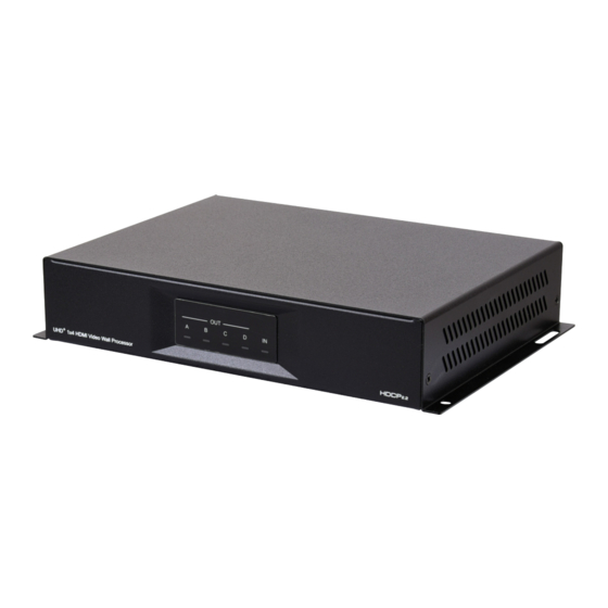
6. OPERATION CONTROLS AND FUNCTIONS 6.1 Front Panel UHD + 1x4 HDMI Video Wall Processor OUT A~D LEDs: These LEDs will illuminate to indicate when a valid sink has been detected on the associated output port. When no sink is detected the LED will remain off. IN LED: This LED will illuminate green to indicate that a live source has been detected on the input port. -
Page 9: Rear Panel
6.2 Rear Panel SERVICE DC 24V RS-232 CONTROL DC 24V Port: Plug the 24V DC power adapter into this port and connect it to an AC wall outlet for power. RS-232 Port: Connect directly to a PC, laptop, or other serial control device to send RS-232 commands to control the unit directly or via PC App. -
Page 10: Rs-232 Pinout And Defaults
6.3 RS-232 Pinout and Defaults Serial Port Default Settings Baud Rate 19200 Data Bits Parity Bits None Stop Bits Flow Control None DE-9 Female Port... -
Page 11: Video Wall App
6.4 Video Wall App The PC based Video Wall App provides complete control over one or more Video Wall Processors via Ethernet or RS-232. This software can scan the local network, as well as any RS-232 connections on the PC, for controllable units to add to the current video wall grouping. Commonly used video wall configurations can be quickly selected or the configuration can be manually set up. -
Page 12: Connection Window
6.4.2 Connection Window By clicking on the “Connection” button at the top-left corner of the main window the “Connection Window” will open up and list all Video Wall Processors that are currently detected on the local network as well as listing all available RS-232 ports on the PC. Each detected unit can then be added to the current video wall layout and assigned a unique ID number. - Page 13 ■ Refresh Button: Click this button to detect any additional units that were added to the network after the window was opened. 2) Selected Units List: All selected units will appear here with an ID number indicating their order to be added to the layout. To re- move an individual unit from the list, click the “x”...
-
Page 14: Layout Tab
3) Connect Button: Clicking this button will activate the software's connection to all units in the Selected Units list, allowing control and configuration of those units. The “Stat” column will show a green circle next to each successfully connected unit. 4) Disconnect Button: Click this button to disconnect the software from all units. - Page 15 1) Video Wall Geometry: This section sets the number of displays used in the video wall. Up to a maximum of 64 displays can be support- ed (8×8 video wall). ■ Column: Sets the number of displays in the video wall, measured horizontally.
-
Page 16: Settings Tab
2) Bezel Settings: Configures the bezel size to compensate for around all displays. Note: Bezel settings assume that the top/bottom and left/right be- zel pairs are uniform in size and all displays in the video wall share the same dimensions. ■... - Page 17 1) System Menu: This window provides information about the select- ed unit’s serial number, and firmware version as well as providing a way to update the firmware or reboot the unit. ■ Serial Number: Displays the unit’s serial number. ■ Firmware Version: Displays the unit’s current firmware version.
- Page 18 3) Input Menu: This window provides control over functions of the unit’s HDMI input including the handling of EDID and HDCP. ■ HDCP Status: Displays the current HDCP status of the unit’s HDMI input. ■ Custom EDID: Click this button to open the Custom EDID Settings window and upload or rename the custom EDID.
- Page 19 ■ Sync Indicator: When a live source is detected, this will be green, when no source is detected it will be grey. ■ EDID Selection: Select the preferred EDID for the unit to use from the dropdown menu. This unit provides the option of six standard EDIDs, four sink sourced EDIDs and one user uploaded EDID.
- Page 20 4) Output Menu: This window provides control over features relating to the unit’s HDMI outputs including the OSD information display, audio output and sync status. Note: These settings affect all 4 outputs. ■ OSD Info: Select the behavior of the informational OSD. Selecting “Off”...
-
Page 21: Telnet Control
6.5 Telnet Control Before attempting to use Telnet control, please ensure that both the unit and the PC are connected to the same active networks. To Access the Command Line Interface (CLI) Click Start, type “cmd” in the search field, and Windows 7 press Enter. -
Page 22: Serial And Telnet Commands
6.6 Serial and Telnet Commands COMMAND Description and Parameters help Show the full command list. help N1 Show details about the specified command. N1 = {Command name} get model name Show the unit's model name. get fw ver Show the unit's current firmware version. set update mcu... - Page 23 COMMAND Description and Parameters get ipaddr Show the unit's current IP address. set netmask N1 Set the unit's static netmask. N1 = X.X.X.X [X = 0~255, Netmask] get netmask Show the unit's current netmask. set gateway N1 Set the unit's static gateway address. N1 = X.X.X.X [X = 0~255, Gateway address] get gateway...
- Page 24 COMMAND Description and Parameters get in 1 edid Show the EDID currently being used on the HDMI input. set edid 7 name N1 Set the name for the specified EDID. N1 = {Name} [32 characters maximum] Note: Only User EDIDs may be renamed. get edid 7 name...
- Page 25 COMMAND Description and Parameters set audio out mute N1 Enable or disable muting the audio output. Available values for N1: [Audio unmuted] [Audio muted] get audio out mute Show the current audio output mute state. get out N1 sync status Show the current sync state of the specified output.
- Page 26 COMMAND Description and Parameters set video wall h bezel compensation N1 Set the video wall’s horizontal bezel compensation value. N1 = 0~50 [Horizontal bezel compensation value] get video wall h bezel compensation Show the video wall’s current horizontal bezel compensation value.
-
Page 27: Connection Diagram
7. CONNECTION DIAGRAM 4K Blu-ray Player HDMI Input Router Power Supply SERVICE DC 24V RS-232 CONTROL RS-232 HDMI Outputs RS-232 Equipped PC/Laptop 2×2 TVs/Displays (Total 4 Screens) -
Page 28: Specifications
8. SPECIFICATIONS 8.1 Technical Specifications HDMI Bandwidth 18Gbps Input Port 1×HDMI (Type-A) Output Ports 4×HDMI (Type-A) Control Ports 1×RS-232 (DE-9) 1×Control (RJ-45) Service Port 1×USB 2.0 (Type A) Baud Rate 19200 Power Supply 24V/1.25A DC (US/EU standards, CE/FCC/UL certified) ESD Protection (HBM) ±8kV (Air Discharge) ±4kV (Contact Discharge) Dimensions (W×H×D) -
Page 29: Video Specifications
8.2 Video Specifications Input Output Supported Resolutions (Hz) HDMI HDMI 720×400p@70/85 640×480p@60/72/75/85 720×480i@60 720×480p@60 720×576i@50 720×576p@50 800×600p@56/60/72/75/85 848×480p@60 1024×768p@60/70/75/85 1152×864p@75 1280×720p@50/60 ... -
Page 30: Audio Specifications
Input Output Supported Resolutions (Hz) HDMI HDMI 2560×1440p@60RB 2560×1600p@60RB 2048×1080p@24/25/30 2048×1080p@50/60 3840×2160p@24/25/30 3840×2160p@50/60 (4:2:0) 3840×2160p@24, HDR10 3840×2160p@50/60 (4:2:0), HDR10 3840×2160p@50/60 4096×2160p@24/25/30 ... -
Page 31: Cable Specifications
8.4 Cable Specifications 1080p 4K30 4K60 (4:4:4) (4:4:4) Cable Length 8-bit 12-bit 8-bit 8-bit High Speed HDMI Cable HDMI Input HDMI Output Bandwidth Category Examples: • 1080p (FHD Video) - Up to 1080p@60Hz, 12-bit color - Data rates lower than 5.3Gbps or below 225MHz TMDS clock •... -
Page 32: Acronyms
9. ACRONYMS ACRONYM COMPLETE TERM Consumer Electronics Control Command-Line Interface DHCP Dynamic Host Configuration Protocol Digital Visual Interface EDID Extended Display Identification Data Gbps Gigabits per second Graphical User Interface HDCP High-bandwidth Digital Content Protection HDMI High-Definition Multimedia Interface High Dynamic Range Internet Protocol Kilohertz Local Area Network... - Page 36 CYPRESS TECHNOLOGY CO., LTD Home page: http://www.cypress.com.tw...
Need help?
Do you have a question about the CDPS-4KQ-AD and is the answer not in the manual?
Questions and answers