Table of Contents
Advertisement
Quick Links
Download this manual
See also:
Operating Manual
Advertisement
Table of Contents

Related Manuals for CYP CDPS-US100R


Summary of Contents for CYP CDPS-US100R
- Page 1 CDPS-US100R HDMI/HDBaseT to Dual HDMI 4K UHD Scaler Operation Manual Operation Manual...
- Page 3 DISCLAIMERS The information in this manual has been carefully checked and is believed to be accurate. Cypress Technology assumes no responsibility for any infringements of patents or other rights of third parties which may result from its use. Cypress Technology assumes no responsibility for any inaccuracies that may be contained in this document.
-
Page 4: Revision History
SAFETY PRECAUTIONS Please read all instructions before attempting to unpack, install or operate this equipment and before connecting the power supply. Please keep the following in mind as you unpack and install this equipment: • Always follow basic safety precautions to reduce the risk of fire, electrical shock and injury to persons. -
Page 5: Table Of Contents
CONTENTS 1. Introduction ............1 2. Applications .............1 3. Package Contents ..........1 4. System Requirements ........2 5. Features ............2 6. Operation Controls and Functions ....3 6.1 Front Panel ..........3 6.2 Rear Panel ..........4 6.3 Remote Control ......... 5 6.4 OSD Menu ..........5 6.5 IR Cable Pin Assignment...... -
Page 6: Introduction
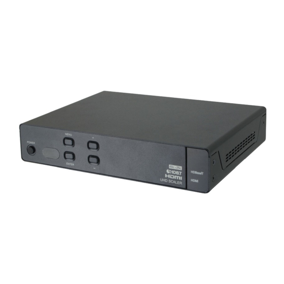
1. INTRODUCTION This HDMI/HDBaseT to Dual HDMI 4K UHD Scaler is designed to extend and scale HDMI signals for simultaneous output to two HDMI displays while also extracting balanced analog audio. It supports 4K@30Hz video, 3D, 36-bit Deep Color, and HD lossless audio as well as other features defined by the latest HDMI specification. -
Page 7: System Requirements
4. SYSTEM REQUIREMENTS • HDMI source equipment such as media players, video game consoles or set-top boxes and/or a compatible HDBaseT Transmitter with 24V PoC support. • HDMI receiving equipment such as HDTVs, monitors or audio amplifiers. • The use of industry standard Cat.6, Cat.6a or Cat.7 cable is highly recommended. -
Page 8: Operation Controls And Functions
6. OPERATION CONTROLS AND FUNCTIONS 6.1 Front Panel MENU POWER HDBaseT HDMI UHD SCALER ENTER POWER & LED: Press this button to power the unit on or place it into stand-by mode. The LED will be lit when the unit is on and receiving power. -
Page 9: Rear Panel
6.2 Rear Panel AUDIO OUT HDMI OUT HDMI IN CAT5e/6/7 SERVICE DC 24V RS-232 9 10 HDMI OUT 1~2: Connect to HDMI TVs, monitors or amplifiers for digital video and audio output. HDMI IN: Connect to HDMI source equipment such as a media player, game console or set-top box. -
Page 10: Remote Control
6.3 Remote Control MENU POWER POWER: Press to power on the unit or place it into stand-by mode. ENTER MENU: Press to open or close the OSD menu. HDMI HDBaseT ▲/▼/◄/►: Within the menu use the UP/ INPUT DOWN keys to move vertically, and use 720P 1080P LEFT/RIGHT to change the settings of a... - Page 11 LEVEL 1 LEVEL 2 LEVEL 3 Output Format (cont.) 1080p@50 1080p@60 1080p@24 4K2K 2048×1080p@24 2048×2080p@50 2048×1080p@60 2048×1152p@60 3840×2160p@24 3840×2160p@25 3840×2160p@30 4096×2160@24 PC-1 640×480@60 640×480@72 640×480@75 800×600@60 800×600@72 800×600@75 1024×768@60 1024×768@72 1024×768@75 PC-2 1280×768@60 1280×800@60 1280×960@60 1280×1024@60 1360×768@60 1366×768@60 1400×1050@60 1440×900@60 1600×900@60 1600×1200@60...
- Page 12 LEVEL 1 LEVEL 2 LEVEL 3 Output Format (cont.) PC-2 1920×1200@60 Native OSD Menu Timer 10 sec 30 sec 60 sec OSD Info Banner Aspect Ratio 16:9 Follow DHCP STATIC Network Status IP Status DHCP MAC Address 0~255 (192.168.1.50) IP Address 0~255 (255.255.255.0) Subnet Mask 0~255 (192.168.1.254)
- Page 13 OSD Menu Descriptions: • Input Source: Input source signal selection. • Output Format: Set output resolution. • OSD Menu Time: Idle time before the OSD menu turns off. • OSD Info Banner: OSD info banner display. • Aspect Ratio: Adjust the output aspect ratio. •...
-
Page 14: Ir Cable Pin Assignment
6.5 IR Cable Pin Assignment IR Blaster Power IR Signal IR Extender IR Signal Power Ground 6.6 RS-232 Protocol UNIT REMOTE CONTROLLER Assignment Assignment ► ◄ Baud Rate: 115200bps Data Bits: 8 Parity: None Flow Control: None Stop Bits: 1... -
Page 15: Rs-232 And Telnet Commands
6.7 RS-232 and Telnet Commands COMMAND DESCRIPTION help Display all available commands. Display all available commands. help N Display command description. N={Command Name} PWON Power on. PWOFF Power off. PWSTA Display power status. VFmtRes Display format status. VFmtRes N Set output video format to any resolution (480i~4K). - Page 16 COMMAND DESCRIPTION 20=640×480p@60 21=1024×768p@72 22=1024×768p@75 23=1280×768p@60 24=1280×800p@60 25=1280×960p@60 26=1280×1024p@60 27=1360×768p@60 28=1366×768p@60 29=1440×900p@60 30=1600×1200p@60 31=1920×1200p@60 32=2048×1080p@24 33=2048×1080p@50 34=2048×1080p@60 35=2048×1152p@60 36=3840×2160p@24 37=3840×2160p@25 38=3840×2160p@30 39=4096×2160p@24 Input N Set input source to HDMI or HDBaseT. N= HDMI, HDBT IPCFG Display IP address configuration. IPDHCP N Turn DHCP mode on/off and get status.
- Page 17 COMMAND DESCRIPTION IPAddUser N N1 Add Telnet user. N=0~9, a~z or A~Z (Up to 20 character) [User name] N1=0~9, a~z or A~Z (Up to 20 character) [Password] IPDelUser N Delete Telnet user. N={User name} IPPort N Set Telnet port. N=1~65535 IPLogin N Set Telnet login requirement and check status.
-
Page 18: Telnet Control
6.8 Telnet Control Before attempting to use Telnet control, please ensure that both the unit and the PC/Laptop are connected to the same active networks. To access Telnet in Windows 7, click on the “Start” menu and type “cmd” in the search field, then press “Enter”. Under Windows XP go to the “Start”... - Page 19 This will connect us to the unit we wish to control. Type “help” to list the available commands. Note: • Commands will not be executed unless followed by a carriage return. Commands are case-sensitive. • If the IP address is changed then the IP address required for Telnet access will also change accordingly.
-
Page 20: Webgui Control
6.9 WebGUI Control Open a web browser on a PC/laptop which is connected to the same LAN as the scaler and type device’s IP address (visible within the OSD menu) into the web address entry bar. The browser will display the WebGUI, providing access to the device’s scaler and system settings. -
Page 21: System Settings
6.9.2 System Settings Click on “System Settings” to change network settings, power the unit on/off or perform a factory reset. -
Page 22: Connection Diagram
7. CONNECTION DIAGRAM REMOTE ZONE Game Console HDMI DVD/Blu-ray Player Input Connection RS-232 In Transmitter HDMI In IR Out HDMI to CAT5e/6 with LAN/IR/RS232 1.5m HDMI Input 60° Cat.5e/6/7 Cable Powered Speakers Balanced Stereo Output Power AUDIO OUT HDMI OUT HDMI IN CAT5e/6/7 SERVICE... -
Page 23: Specifications
8. SPECIFICATIONS 8.1 Technical Specifications Video Bandwidth 340MHz/10.2Gbps Input Ports 1×HDMI 1×Cat.5e/6/7 1×IR Extender (3.5mm) Output Ports 2×HDMI 1×Balanced Stereo Audio (5-pin Terminal Block) 1×IR Blaster (3.5mm) Control Interfaces 1×IP Control (RJ45) 1×RS-232 (5-pin Terminal Block) Supported Resolutions 480i@60Hz - 4K@24/25/30Hz VGA@60Hz - WUXGA@60Hz (RB) HDMI Cable Length 10m (1080p@60Hz, 12-bit) -
Page 24: Video Specifications
Weight 1,136g Chassis Material Metal Silkscreen Color Black Operating Temperature 0˚C - 40˚C/32˚F - 104˚F Storage Temperature −20˚C - 60˚C/−4˚F - 140˚F Relative Humidity 20 - 90% RH (Non-condensing) Power Consumption 15W/25W (with PoC Transmitter connected) 8.2 Video Specifications Supported PC Resolutions (Hz) Input Output 640×480@60/72/75... -
Page 25: Hdbaset Specifications
Supported TV Resolutions (Hz) Input Output 720×480i@60 720×480p@60 720×576i@50 720×576p@50 1280×720p@50/60 1920×1080i@50/60 1920×1080p@50/60 1920×1080p@24/25/30 2048×1080p@24/50/60 2048×1152p@60 3840×2160p@24/25/30 4096×2160p@24 ... -
Page 26: Acronyms
9. ACRONYMS ACRONYM COMPLETE TERM Cat.5e Category 5 (enhanced) Cable Cat.6 Category 6 Cable Cat.7 Category 7 Cable Command Line Interface Digital Visual Interface EDID Extended Display Identification Data Graphical User Interface High-Definition HDCP High-bandwidth Digital Content Protection HDMI High-Definition Multimedia Interface Internet Protocol Infrared LPCM... - Page 28 CYPRESS TECHNOLOGY CO., LTD. www.cypress.com.tw...
Need help?
Do you have a question about the CDPS-US100R and is the answer not in the manual?
Questions and answers