
Related Manuals for GEM 3030 mFlow


Summary of Contents for GEM 3030 mFlow
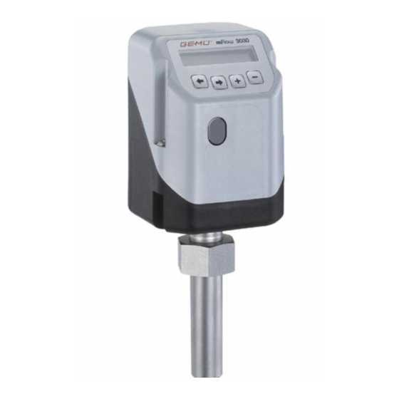
- Page 1 3030 mFlow Magnetically inductive fl owmeter OPERATING INSTRUCTIONS Status 25.10.18 From version 1.2.2.1 3030 mFlow...
-
Page 2: Table Of Contents
Diagrammatic view of the outputs Assembly / disassembly Assembly 4.1.1 Assembly with GEMÜ weldolet 4.1.2 Assembly with GEMÜ grommet 4.1.3 Assembly with GEMÜ wafer-type fl ange 4.1.4 Assembly with Tuchenhagen Varivent in-line ® housing 4.1.5 Assembly with Neumo BioControl in-line housing ®... -
Page 3: General Safety Information
Ensure that all members of personnel operating instructions are only applicable in Germany. If understand the safety instructions. the GEMÜ 3030 mFlow is used in other countries, the local ● Ensure that the power supply equipment is applicable regulations must be observed. When dealing with electrically safe. -
Page 4: Correct Use
1.4 Correct use 2.4 Function 7 The GEMÜ 3030 mFlow is suitable for use as defined in the The magnetically inductive fl owmeter GEMÜ 3030 mFlow is datasheet. In order to ensure correct product function, the suitable for electrically conductive media (conductivity ≥ 20 μS/ following notes should be observed. -
Page 5: Diagrammatic View Of The Outputs
• Freely programmable alarm outputs Operating parameters Current output of the fl owmeter 4-20 mA Binary outputs/pulse output 24 V DC RS 232 Supply voltage 24 V DC Profi bus DP (optional) Infrared (under development) Operation Keypad 3030 mFlow 5 / 40... -
Page 6: Assembly / Disassembly
4.1 Assembly Preferred installation position Before installing the GEMÜ 3030 mFlow in the piping, drain and cool the piping to avoid caustic burns from the medium and scalding. The sensor should preferably be installed in a vertical rising pipeline with an upwards flow direction. -
Page 7: Assembly With Gemü Weldolet
3. Use the union nut (M33x2, SW36) to attach the fl owmeter on the in-line housing. 4.1.3 Assembly with GEMÜ wafer-type fl ange 1. Install the wafer-type fl ange in the line. 2. Attach the fl owmeter (ensure that the locking wing is not twisted). -
Page 8: Electrical Connections
6.2.1 Working level (Mode) In the case of the Profibus DP design, the RS-232 The GEMÜ 3030 mFlow is automatically at this level after the interface is omitted. supply voltage is switched on. 6.2.2 Confi guration level (Setup) ●... -
Page 9: Commissioning
Commissioning The GEMÜ 3030 mFlow fl owmeter is calibrated at the factory and is therefore immediately ready for operation once the operating voltage is connected. 1. Set the unit of measure (SetBasics/Unit). 2. Set the mains frequency (SetBasics/F.Line). 3. Set the analogue output (SetFunction/Analog Output). -
Page 10: Confi Guration Menu (Setup)
This menu is used to read out all information/diagnostics regarding the fl owmeter, the connected signals and any errors that occur. 2. SetBasics SetBasics is used to set the basic settings for the GEMÜ 3030 mFlow, such as the selection of the measuring range, display settings and resetting to factory settings. -
Page 11: Menu Structure 1 Service
10.3 Menu structure 1 Service 3030 mFlow 11 / 40... -
Page 12: Menu Structure 2 Setbasics
10.4 Menu structure 2 SetBasics 3030 mFlow 12 / 40... -
Page 13: Menu Structure 3 Setfunction
10.5 Menu structure 3 SetFunction 3030 mFlow 13 / 40... -
Page 14: Menu Structure 4 Setcalibration
10.6 Menu structure 4 SetCalibration 3030 mFlow 14 / 40... -
Page 15: Parameter Table
Setting the display lighting OnKey / On OnKey Time for an automatic return to AutoReturn 1 to 60 min 5 min the working level HelpLanguage Text language D / GB HelpText Display the help text ON / OFF 3030 mFlow 15 / 40... - Page 16 0 °C ± 90,000,000 l/h / 5000 l/h / AlarmMaxK3 Value for the max. alarm K3 0 to 100 °C 0 °C Determines the delay time of K3 delay 0 to 100 s relay K3 3030 mFlow 16 / 40...
- Page 17 Calculate the non-calibrated Calculate measuring ranges CorrFactor Change of fl ow rate value 0.1... 999.9 100.0 % Configuration level Display Function Value range Factory setting 5 Communication IR-Port Status DP addr Input the Profibus DP address 3030 mFlow 17 / 40...
-
Page 18: Explanation Of Parameters
Login I / O Status In certain areas, various codes are used to protect the confi guration level on the GEMÜ 3030 mFlow against improper changing of parameters. All menu items are marked by symbols indicating their write and read protection. - Page 19 The codes for operation via the RS232-interface can only be assigned, activated or deactivated via the RS232-interface. The codes for direct operation via the GEMÜ 3030 mFlow keypad can only be assigned, activated or deactivated via the keypad on the unit itself.
-
Page 20: Reading Out, Deleting And Deactivating Error Messages
12.1.4 Display serial number, software version and ID, and enter TAG number SETUP Service SetBasics SetFunction SetCalibration Communication Return Diagnosis Login Gemü specific I / O Status V:X.X.X.X: Displays the current software release. S/N: Displays the fl owmeter serial number. 3030 mFlow 20 / 40... -
Page 21: Setbasics
Set the leak fl ow rate suppression as a % of the measuring range. No measurement signal is output in the set range. Filter: Input the fi lter constants for value smoothing. F.Line: Input the mains frequency. 3030 mFlow 21 / 40... -
Page 22: Setfunction
Determines the delay time of relay K2. Sets the lower trigger threshold under which output K1 is switched. AlarmMaxK1: Sets the upper trigger threshold over which output K1 is switched. K1 delay: Determines the delay time of relay K1. 3030 mFlow 22 / 40... -
Page 23: Setting The Error Time And Error Action
Warning Warning message P4: Memory 4 Pulse Activate the pulse output W: Factory setting The GEMÜ 3030 mFlow automatically stores all parameters in AlarmMinK3: working memory P1. Sets the lower trigger threshold under which output K3 is switched. AlarmMaxK3: Sets the upper trigger threshold over which output K3 is switched. -
Page 24: Setcalibration
When calibrating the measuring ranges, the largest should be taken fi rst (measuring range 4). Only for GEMÜ fi tting types. Input the inside diameter of If it is not possible to calibrate a measuring range, this can the piping. The calibrated values are forecast by the GEMÜ... -
Page 25: Error Messages
Ensure the correct flow direction m/s) All error messages can be read in the menu item ErrorList (1 Service / 1.3 Diagnosis). The menu item ClearErrorList (1 Service/ 1.3 Diagnosis) can be used to clear the internal error memory. 3030 mFlow 25 / 40... - Page 26 Input of the pulses/litres 1 Pulse/l Output l/Pulse Input of the litres/pulses 1 l/Pulse Determines the delay time between Error Time 0,2 s error recognition and error message Iout onWar Status of the current output > 20 mA 3030 mFlow 26 / 40...
-
Page 27: Disposal
Pay attention to adhered residual material and gas diffusion from penetrated media. 16 Returns Clean the flowmeter. Request a return delivery note from GEMÜ. Returns must be made with a completed return delivery note. If not completed, GEMÜ cannot process... -
Page 28: Overview Of Types
Complete measurement device Separate measurement device Separate fi tting Assembly 3030 ... DD... 3030 ... ZD... 3030 ... KD GEMÜ wafer-type fl ange Complete measurement device Separate measurement device Separate fi tting Assembly 3030 ... DF... 3030 ... ZF... 3030 ... KF... - Page 29 No (not short-circuit proof) Pulse output Type of contact Switching voltage Drop voltage max. 2V at 500 mA Switching current max. 500 mA Switching frequency max. 500 Hz Current limitation Particulars Pulse pause ratio 1:1 3030 mFlow 29 / 40...
- Page 30 Reference conditions Factory calibration with water at 25 °C, 0.1 m/s < v < 10 m/s GEMÜ 3030 with GEMÜ in-line housing 1 %* of active end value of measuring range (under reference conditions) GEMÜ 3030 with GEMÜ wafer-type flange 1 %* of active end value of measuring range (under reference conditions) GEMÜ...
- Page 31 FPM, EPDM, Isolast J9505 Flow characteristics 10.000.000 DN 300 DN 250 DN 200 1.000.000 DN 150 DN 125 DN 100 DN 80 DN 65 100.000 DN 50 DN 40 DN 32 DN 25 10.000 1.000 Flow velocity m/s 3030 mFlow 31 / 40...
- Page 32 20.1 Order data complete measurement device Housing configuration Code Sensor material Code Measurement device with GEMÜ in-line housing 1.4435 / PEEK Measurement device with GEMÜ wafer-type flange 1.4435 / TFM 16 Measurement device with GEMÜ weldolet Measurement device with Neumo BioControl ®...
- Page 33 Code Device version Code Separate measurement device for Measurement device, with field bus interfaces GEMÜ in-line housing (only for Option DP) Separate measurement device for Measurement device 4 - 20 mA, 1 pulse output, GEMÜ wafer-type flange 2 relay outputs (not for Option DP)
- Page 34 (only housing configuration KD, KU, KN) EPDM (only housing configuration KU, KN) Connection Code GEMÜ weldolet (only housing configuration KH) Union end with insert (threaded socket Rp) K-Number Code DIN wafer-type flange (only housing configuration KF) Ra ≤ 0.8 μm electropolished (internal/external)
- Page 35 21 Dimensions 21.1 Dimensions of fl owmeter 3030 mFlow 35 / 40...
- Page 36 21.2 Dimensions of installation fi ttings GEMÜ in-line housing 87.0 Rp 1 48.5 G 1 1/2 89.0 Rp 1 1/4 60.0 91.8 Rp 1 1/2 66.0 G 2 1/4 95.8 Rp 2 81.5 G 2 3/4 101.5 Rp 2 1/2 101.0...
- Page 37 GEMÜ weldolet M33x2 ø32,8 Tuchenhagen VARIVENT in-line housing ® ød øD Neumo BioControl in-line housing ® Ø um 45° Ø drawn 45° offset versetzt gezeichnet! øD øU ød 50.1 50.1 3030 mFlow 37 / 40...
- Page 38 X1 connector 8 Errors 20 Explanation of parameters 18 Explanation of signs 3 Fehlermeldungen 25 Function 4 GEMÜ CONEXO 4 HelpLanguage 15, 21, 26 HelpText 15, 21, 26 hrs 15, 20 K1 Fn 16, 26 K1 Switch 16, 22, 26...
- Page 39 3030 mFlow 39 / 40...
- Page 40 GEMÜ Gebr. Müller Apparatebau GmbH & Co. KG · Fritz-Müller-Str. 6-8 · D-74653 Ingelfi ngen-Criesbach Telefon +49(0)7940/123-0 · Telefax +49(0)7940/123-192 · info@gemue.de · www.gemu-group.com...
Need help?
Do you have a question about the 3030 mFlow and is the answer not in the manual?
Questions and answers