GEM 1235 Operating Instructions Manual
Electrical position indicator
Hide thumbs
Also See for 1235:
- Operating instructions manual (60 pages) ,
- Operating instructions manual (22 pages)

Related Manuals for GEM 1235


Summary of Contents for GEM 1235
- Page 1 GEMÜ 1235 24V / IO-Link, 3E, 4E Electrical position indicator Operating instructions further information webcode: GW-1235...
- Page 2 All rights including copyrights or industrial property rights are expressly reserved. Keep the document for future reference. © GEMÜ Gebr. Müller Apparatebau GmbH & Co. KG 16.11.2022 GEMÜ 1235 2 / 26 www.gemu-group.com 24V / IO-Link, 3E, 4E...
-
Page 3: Table Of Contents
1 General information ..........Information ............ Symbols used ..........Warning notes ..........2 Safety information ..........3 Product description ..........4 GEMÜ CONEXO ............ 5 Correct use ............6 Order data ............7 Technical data ............. 8 Dimensions ............9 Manufacturer's information ........ -
Page 4: General Information
▶ Non-observance can cause death or severe injury. WARNING Potentially dangerous situation! ▶ Non-observance can cause death or severe injury. CAUTION Potentially dangerous situation! ▶ Non-observance can cause moderate to light injury. GEMÜ 1235 4 / 26 www.gemu-group.com 24V / IO-Link, 3E, 4E... - Page 5 Potentially dangerous situation! ▶ Non-observance can cause damage to property. The following symbols for the specific dangers can be used within a warning note: Symbol Meaning Danger of explosion! www.gemu-group.com 5 / 26 GEMÜ 1235 24V / IO-Link, 3E, 4E...
-
Page 6: Safety Information
13. Maintain the product correctly. 14. Do not carry out any maintenance work and repairs not described in this document without consulting the manufacturer first. In cases of uncertainty: 15. Consult the nearest GEMÜ sales office. GEMÜ 1235 6 / 26 www.gemu-group.com... -
Page 7: Product Description
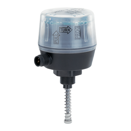
3 Product description 3 Product description 3.1 Construction Item Name Materials Housing cover Housing base PVDF Electrical connection PVDF Adapter piece PVDF Mounting kit, valve specific Stainless steel Seals EPDM, PUR www.gemu-group.com 7 / 26 GEMÜ 1235 24V / IO-Link, 3E, 4E... - Page 8 CLOSED ERROR OPEN High visibility LED Valve in OPEN position Valve in CLOSED position Programming mode OPEN / CLOSED flash alternately flashes alternately LED conditions lit (on) irrelevant flashes GEMÜ 1235 8 / 26 www.gemu-group.com 24V / IO-Link, 3E, 4E...
- Page 9 3.4 Function The GEMÜ 1235 electrical position indicator shows the position of the valve. When the valve is opened, the spindle in the elec- trical position indicator moves upwards and indicates that the valve is OPEN using the high visibility LEDs and communication interface.
-
Page 10: Gemü Conexo
The product is not intended for use in potentially explosive areas. The product is designed for fitting to a GEMÜ valve in order to detect the position of linear actuators visually and electrically. The product has a microprocessor controlled intelligent position sensor as well as an analogue travel sensor system (poten- tiometer) which is positively connected with the actuator spindle by means of a mounting kit (spring, operating bush). -
Page 11: Order Data
M125 M12 plug, 5-pin 6 Travel sensor version Potentiometer, 30 mm length 7 Housing material PVDF base, black, PPR natural cover, M16 thread PEEK 8 Special version UL approval www.gemu-group.com 11 / 26 GEMÜ 1235 24V / IO-Link, 3E, 4E... -
Page 12: Technical Data
0 — 40 °C 7.2 Product compliance EMC Directive: 2014/30/EU SIL: Product description: Electrical position indicator GEMÜ 1235 Device type: Valid software version: V1.0.0.4 Safety function: The safety function is defined as a High (24 V DC) signal at pin 5 (device version 3S/4S) and at pin 4 (device ver-... -
Page 13: Dimensions
8 Dimensions ø 60 TURN SW 27 Travel sensor version Code 65.5 87.5 112.5 30.5 55.5 19.0 41.0 66.0 Dimensions in mm www.gemu-group.com 13 / 26 GEMÜ 1235 24V / IO-Link, 3E, 4E... -
Page 14: Manufacturer's Information
2. Avoid UV rays and direct sunlight. 3. Do not exceed the maximum storage temperature (see chapter "Technical data"). 4. Do not store solvents, chemicals, acids, fuels or similar fluids in the same room as GEMÜ products and their spare parts. 10 Assembly and installation 10.1 Preparations for installing the valve (linear actuator) -
Page 15: Mounting Kit Assembly (Quarter Turn Actuator)
2. Secure the bracket 3 to the retaining feet as shown. In doing so, the tap shaft must sit free of play in the shaft of the actu- ator. www.gemu-group.com 15 / 26 GEMÜ 1235 24V / IO-Link, 3E, 4E... - Page 16 10.7 Installing the electrical position indicator (linear actuator) CAUTION Incorrect installation of the product. ▶ Damage to the housing. Only tighten the product using the spanner flats provided for this purpose. ● 9 (SW 27) GEMÜ 1235 16 / 26 www.gemu-group.com 24V / IO-Link, 3E, 4E...
- Page 17 10.8 Installing the electrical position indicator (quarter turn actuator) CAUTION Incorrect installation of the product. ▶ Damage to the housing. Only tighten the product using the spanner flats provided for this purpose. ● www.gemu-group.com 17 / 26 GEMÜ 1235 24V / IO-Link, 3E, 4E...
-
Page 18: Electrical Connection
The end positions can be programmed as follows: - On-site programming - Programming input (pin 5) - Communication interface When programming via the communication interface, automatic programming is recommended. GEMÜ 1235 18 / 26 www.gemu-group.com 24V / IO-Link, 3E, 4E... - Page 19 4. Open valve until end position is reached. 5. Close valve until end position is reached. 6. Turn the housing cover back clockwise and press it down. ð The end positions are set. www.gemu-group.com 19 / 26 GEMÜ 1235 24V / IO-Link, 3E, 4E...
-
Page 20: Initialization Of The End Positions Via Io-Link
4. Close valve until end position is reached. 5. Programming mode is automatically terminated if the valve does not move for 5 seconds. ð The end positions are set. GEMÜ 1235 20 / 26 www.gemu-group.com 24V / IO-Link, 3E, 4E... -
Page 21: Troubleshooting
Sensor error OPEN position CLOSED position Short-circuit Output OPEN signal output Output CLOSED OPEN+CLOSED Internal error OPEN and CLOSED flash simultaneously Supply voltage too low lit (on) irrelevant flashes www.gemu-group.com 21 / 26 GEMÜ 1235 24V / IO-Link, 3E, 4E... - Page 22 Communication disturbed or interrupted Check the wiring Supply voltage too low Supply voltage too low Ensure supply voltage in accordance with chapter "Technical data" Internal error Memory error Return device GEMÜ 1235 22 / 26 www.gemu-group.com 24V / IO-Link, 3E, 4E...
-
Page 23: Inspection And Maintenance
Returned goods can be processed only when this note is completed. If no return deliv- ery note is included with the product, GEMÜ cannot process credits or repair work but will dispose of the goods at the operator's expense. -
Page 24: Declaration Of Conformity According To 2014/30/Eu (Emc Directive)
18 Declaration of conformity according to 2014/30/EU (EMC Directive) EU Declaration of Conformity in accordance with 2014/30/EU (EMC Directive) GEMÜ Gebr. Müller Apparatebau GmbH & Co. KG Fritz-Müller-Straße 6-8 74653 Ingelfingen-Criesbach, Germany declare that the product listed below complies with the safety requirements of the EMC Directive 2014/30/EU. -
Page 25: Ul Certificate
PROCESS CONTROL EQUIPMENT, ELECTRICAL This certificate confirms that representative samples of Open Type Electro-Pneumatic Positioner/Controller models: 1235, 1236, and 1436 Eco Have been investigated by UL in accordance with the Standard(s) indicated on this Certificate. UL 61010-1 Safety Requirements For Electrical Equipment... - Page 26 GEMÜ Gebr. Müller Apparatebau GmbH & Co. KG Fritz-Müller-Straße 6-8, 74653 Ingelfingen-Criesbach, Germany Subject to alteration Phone +49 (0) 7940 1230 · info@gemue.de www.gemu-group.com 11.2022 | 88601591...
Need help?
Do you have a question about the 1235 and is the answer not in the manual?
Questions and answers