
Subscribe to Our Youtube Channel
Related Manuals for GEM 3040


Summary of Contents for GEM 3040
- Page 1 GEMÜ 3040 Ultrasonic flowmeter Operating instructions further information webcode: GW-3040...
- Page 2 All rights including copyrights or industrial property rights are expressly reserved. Keep the document for future reference. © GEMÜ Gebr. Müller Apparatebau GmbH & Co. KG 18.11.2020 GEMÜ 3040 2 / 34 www.gemu-group.com...
-
Page 3: Table Of Contents
15 Removal from piping ..........29 16 Disposal ..............29 17 Returns ..............29 18 Annex ............... 29 19 Declaration of conformity according to 2014/30/EU (EMC Directive) ............32 20 Manufacturer's declaration ........33 www.gemu-group.com 3 / 34 GEMÜ 3040... -
Page 4: General Information
6. Define the areas of responsibility. CAUTION 7. Observe the safety data sheets. Potentially dangerous situation! 8. Observe the safety regulations for the media used. ▶ Non-observance can cause moderate to light injury. GEMÜ 3040 4 / 34 www.gemu-group.com... -
Page 5: Product Description
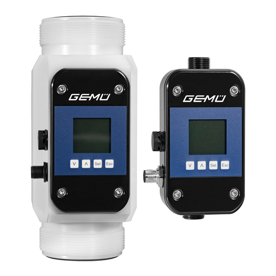
Seals EPDM 3.2 Description The GEMÜ 3040 is an ultrasonic flowmeter which determines the volumetric flow of conductive and non-conductive liquids in a contact-free manner. The flowmeter is suitable for al- kaline, toxic and corrosive media and can also be used for DI water. -
Page 6: Product Label
The flow volume is determined from the flow ve- locity and the known pipe diameter. Specification The month of manufacture is encoded in the product type/or- der code and can be obtained from GEMÜ. The product was manufactured in Germany. Receiver/ Transmitter/... -
Page 7: Order Data
PE-HD 6 Seal material Code EPDM 7 Electrical connection Code M12 x 1 plug, 5-pin 8 Voltage/frequency Code 24 V DC 9 Display Code With display 10 Output Code 5-pin plug with 1-wire communication www.gemu-group.com 7 / 34 GEMÜ 3040... -
Page 8: Technical Data
0 to 16 bar Pressure rating: DN 10–15: PN16 DN 20–50: PN10 Pressure loss: Pressure loss with water at 22 °C, 100 kPa = 1 bar DN25 (code 25) Flow [l/min] DN32 (code 32) Flow [l/min] GEMÜ 3040 8 / 34 www.gemu-group.com... - Page 9 DN 50: 1300 g Measuring range: DN 10: 0.3–21.0 l/min DN 15: 0.9–36.0 l/min DN 20: 3.5–60.0 l/min DN 25: 5.0–240.0 l/min DN 32: 9.0–300.0 l/min DN 40: 18.0–480.0 l/min DN 50: 36.0–900.0 l/min www.gemu-group.com 9 / 34 GEMÜ 3040...
- Page 10 Supply voltage: 24 V DC (-5/+10%) Electrical connection 1 x 5-pin M12 connector type: Reverse battery protec- tion: Outputs: One digital output (optionally adjustable as pulse or alarm) One analogue output (current output 0/4–20 mA) GEMÜ 3040 10 / 34 www.gemu-group.com...
-
Page 11: Dimensions
7 Dimensions 7 Dimensions Connection Channel offset G1/2 G3/4 84.5 94.2 G1¼ 98.5 G2¼ G2¾ Dimensions in mm www.gemu-group.com 11 / 34 GEMÜ 3040... -
Page 12: Manufacturer's Information
4. Do not store solvents, chemicals, acids, fuels or similar Use appropriate, functional and safe tools. ● fluids in the same room as GEMÜ products and their spare 1. Ensure the product is suitable for the relevant application. parts. 2. Check the technical data of the product and the materials. -
Page 13: Installation Position
Process valve GEMÜ 3040 BOTTOM -> inlet GEMÜ 3040 Fig. 4: Ideal installation position of the product To ensure gas is detected as quickly as possible, it is import-... - Page 14 This means that the heat can be emitted upwards and the load on the device's electronics is reduced. It must generally GEMÜ 3040 be ensured that no external heat sources are additionally GEMÜ acting on the measurement device.
-
Page 15: Electrical Connection
Plug assignment, 5-pin, with output assignment at the factory The inputs and outputs can be reprogrammed specific to application. Signal name Uv, 24 V DC supply voltage Pulse output Uv, GND supply voltage Communication Analogue output www.gemu-group.com 15 / 34 GEMÜ 3040... -
Page 16: Commissioning
This en- ▶ The GEMÜ 3040 measurement device may only be oper- sures that only authorized employees can make changes to ated within the limits specified on the product label and in the device parameters. - Page 17 Start screen Pulse valence L/h + L L/min + m Operating quantity counter Daily quantity counter Gal/min + Gal L/min + L Units Display Display filter 0° 270° 180° 90° Turn display Alarm flashing www.gemu-group.com 17 / 34 GEMÜ 3040...
- Page 18 PNP break contact Empty pipe Pulse output Digital output 2 Function Dosing Negative flow Low set point High set point PNP make contact NPN break contact Transistor logic NPN make contact PNP break contact = inactive GEMÜ 3040 18 / 34 www.gemu-group.com...
- Page 19 SW Ver DE Ver Fac.no.: Diagnostics HW Ver Versions Flow input Test flow Stop Start Values Eamp Rohf Temp. Control PCK1 PCK2 PCK3 PCK4 PCK5 PCK6 Status Flag0 Flag1 Flag2 PuMo Pump mode = inactive www.gemu-group.com 19 / 34 GEMÜ 3040...
-
Page 20: Measurement Device Functions And Default Settings
5.0 l/min for DN25 11.2.3.1 1-point correction – 9.0 l/min for DN32 Setting range: -50.0 to 50.0% in steps of 0.1% – 18.0 l/min for DN40 Factory setting: 0% – 36.0 l/min for DN50 GEMÜ 3040 20 / 34 www.gemu-group.com... - Page 21 The low set point for the digital output is set here. Setting range: 0 to 8000 ml/s in steps of 0.01 ml/s. 0 to 900 l/min in steps of 0.01 l/min. Factory setting: 0 www.gemu-group.com 21 / 34 GEMÜ 3040...
- Page 22 The operating quantity counter cannot be set to zero. Rounding error +0.12% Once the daily quantity counter has reached 1,000,000 gal, it starts counting again at zero. However, the operating quantity counter continues to run without reset. GEMÜ 3040 22 / 34 www.gemu-group.com...
- Page 23 Current [mA] menu. Less than 0% 0% (min. range) Between 0% and Linear interpolation of 0 to 20 mA GEMÜ 3040 100% 100% (max. range) 20 Greater than 100% – 4 to 20 mA For the representation, the "Min. range" was used as 0% and the "Max.
- Page 24 Setting range: 0 to 8000 ml/s (or °C or m/s) + 0 to 900 l/min in steps of 0.01 Time [s] Factory setting: 0 ml/s Fig. 16: Filter strength function of the analogue output Filter 100% 16 ms Weak 0.3 s Medium Strong 30 s GEMÜ 3040 24 / 34 www.gemu-group.com...
- Page 25 ▶ In the case of an inductive load, for example, a relay, an contact ance ance additional recovery diode must be installed antiparallel to the load. PNP make High-resist- High-resist- 24 V pulses contact ance ance www.gemu-group.com 25 / 34 GEMÜ 3040...
-
Page 26: Overview Of Factory Settings
Fig. 18: Connection of the digital output to relay If pumping is pulsating, the measurement device sets the dis- Example 2: GEMÜ 3040 via PNP, external counter for example play and analogue filter to strong. When pulsating pumping stops, the device behaves as set again. -
Page 27: General Information
The The following measures must be taken before sending the measurement device achieves maximum accuracy after a GEMÜ 3040 flowmeter for repair work: time period of 30 minutes with the auxiliary power switched WARNING The product is ready for operation. -
Page 28: Error Messages
30 sec starting up or with air bubbles. The mes- sage remains visible for 30 sec even when the flow is back within the permiss- ible range. However, the measurement then works again immediately. GEMÜ 3040 28 / 34 www.gemu-group.com... -
Page 29: Inspection/Maintenance
Returned goods can be processed only when this note is completed. If no return delivery note is included with the product, GEMÜ cannot process credits or repair work but will dispose of the goods at the operator's expense. - Page 30 -02.0% must be entered for the 1-point cor- rection. Display Units Number of key activa- Display indication tions Display Dosing Turn display Media Display Gen. settings Turn display Display 0° GEMÜ 3040 30 / 34 www.gemu-group.com...
- Page 31 Number of key activa- Display indication tions Display Turn display 90° Display Turn display 90° Carried out In order to reset the display back to the delivery state, 0 ° must be selected for "Turn display". www.gemu-group.com 31 / 34 GEMÜ 3040...
-
Page 32: Declaration Of Conformity According To 2014/30/Eu (Emc Directive)
19 Declaration of conformity according to 2014/30/EU (EMC Directive) EU Declaration of Conformity in accordance with 2014/30/EU (EMC Directive) GEMÜ Gebr. Müller Apparatebau GmbH & Co. KG Fritz-Müller-Straße 6-8 74653 Ingelfingen-Criesbach, Germany declare that the product listed below complies with the safety requirements of the EMC Directive 2014/30/EU. -
Page 33: Manufacturer's Declaration
Additional information: The products are developed and produced according to GEMÜ process instructions and quality standards which comply with the requirements of ISO 9001. In accordance with Article 4, Paragraph 3 of the Pressure Equipment Directive 2014/68/EU, these products must not be identi- fied by a CE label. - Page 34 Subject to alteration GEMÜ Gebr. Müller Apparatebau GmbH & Co. KG *88714520* Fritz-Müller-Straße 6–8, 74653 Ingelfingen-Criesbach, Germany 11.2020 | 88714520 Phone +49 (0) 7940 1230 · info@gemue.de www.gemu-group.com...
Need help?
Do you have a question about the 3040 and is the answer not in the manual?
Questions and answers