Table of Contents
Advertisement
Quick Links
Advertisement
Table of Contents

Related Manuals for AMGO HS-12


Summary of Contents for AMGO HS-12
- Page 1 TWO POST LIFT Model: HS-12...
-
Page 3: Table Of Contents
CONTENTS Product Features and Specifications ...........1 Installation Requirement ..............3 Installation Steps ................4 Exploded View ................24 Test Run ..................27 Operation Instruction ..............29 Maintenance ................29 Trouble Shooting ................30 Parts List ..................31... -
Page 5: Product Features And Specifications
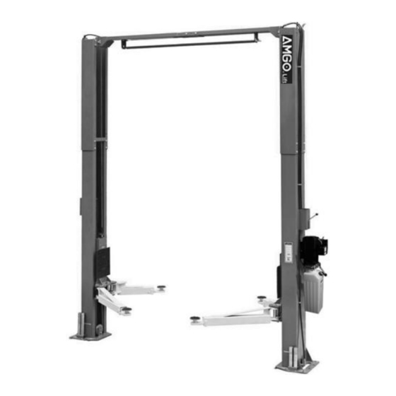
I. PRODUCT FEATURES AND SPECIFICATIONS CLEAR-FLOOR HYDRAULIC-DRIVED MODEL FEATURES Model HS-12 (See Fig. 1) · Direct-drived design, minimize the lift wear parts and breakdown ratio · Dual hydraulic cylinders, designed and made on ANSI standards, utilizing NOK oil seal in cylinder ·... - Page 6 Arm Swings View For Model HS-12 Fig. 2...
-
Page 7: Installation Requirement
II. INSTALLATION REQUIREMENT A. TOOLS REQUIRED Rotary Hammer Drill (Φ19) Carpenter’s Chalk Screw Sets Hammer Tape Measure (295-1/4”) Level Bar Pliers English Spanner (12") Socket Head Wrench (3 Ratchet Spanner With Socket (28 Lock Wrench ... -
Page 8: Installation Steps
A. Location of installation Check and ensure the installation location (concrete, layout, space size etc.) is suitable for lift installation. B. Use a carpenter’s chalk line to establish installation layout of base plate (See Fig. 5). Model HS-12 Chalk Line (150-3/4”) Fig. 5... - Page 9 C. Check the parts before assembly. 1. Packaged lift and hydraulic power unit ( See Fig. 6). Fig. 6 2. Move the lift aside with a fork lift or hoist, and open the outer packing carefully, check the parts according to shipment list. (See Fig.
- Page 10 4. Lift the lower column with a fork lift or hoist, take down the package stand, than take off the lower extension column, take out the parts in the inner column (See Fig. 9). Fig. 9 5. Move aside the parts and check the parts according to the shipment parts list (See Fig.
- Page 11 6. Check the parts of the parts bag 1 according to parts bag list (See Fig. 12). Fig. 12 Check the parts of the parts bag 2 according to parts bag list (See Fig. 13). Fig. 13 Check the parts of the parts bag 3 according to parts bag list (See Fig.
- Page 12 D. Install parts of extension columns (See Fig. 15). Fig. 15...
- Page 13 E. Install hydraulic cylinder Connecting the extended straight fitting and 90° fitting to the cylinders, and then install the cylinder in the carriages (See Fig. 16) Offside column Powerside column Cylinder installed the joint and put into the column. Wind enough White wrap Fig.
- Page 14 This lift is designed with 2-section columns. Adjustable height according to the ceiling height while connecting the extension columns. For model HS-12 1. When the ceiling height is over 177-1/8”, connecting the extension columns with the lower holes (See Fig.
- Page 15 2. When the ceiling height is less than 165-1/4”, connecting the extension columns with the upper holes (See Fig.18) Fig. 18 Low Setting...
- Page 16 G. Position columns Position the columns on the installation layout of baseplate. Install the anchor bolts. Check the columns plumbness with level bar, and adjusting with the shims if the columns are not vertical. Do not tighten the anchor bolts (See Fig.19) Width between columns:123-1/2”...
- Page 17 H. Install overhead top beam 1. With help of the hook of top beam, put one side of top beam on top of the extension column and connecting the top beam to extension column by bolts, tighten the bolts. Then assemble the connecting bracket (See Fig.
- Page 18 2. Assemble overhead top beam, tighten the columns anchor bolts (See Fig. 21) Tighten the anchor bolts with ratchet spanner with socket. Note: Torque of Anchors is 150N.m. Tighten Fig.21...
- Page 19 I. Installing the limit switch control bar and limit switch (See Fig. 22). Note: Wire of limit switch should be protected by protecting plastic hose. Use 3# Hex wrench loosen drive rod screw and adjust the drive rod. Blue wire connect 11# Connecting terminal, the other end connect wire for...
- Page 20 J. Install safety device (See Fig. 23 & Fig. 24 Fig. 23 Powerside safety device Fig. 24 Offside safety device...
- Page 21 K. Lift the carriages up by hand and make them be locked at the same level (See Fig. 25). Fig. 25...
- Page 22 L. Install power unit (See Fig. 26) Fig. 26 Note: In consideration of Hydraulic Power Unit’s durability and keep the equipment running in the perfect condition, please use Hydraulic Oil 46#.
- Page 23 M. Install oil hose At high setting and low setting oil hose connection (See Fig. 27) Oil hose and wire pass through the support bracket Oil hose pass through the wire tube on top beam Straight fitting connect the oil hose Fig.
- Page 24 N. Install safety cable. Install safety cable from offside safety assy. to powerside safety assy., pass through the top beam (See Fig. 28) Safety cable pass through small pulley bracket Safety cable Install safety cable from offside safety assy. Safety cable connected with the powerside safety assy.
- Page 25 O. Install retainer (See Fig. 29). Install retainer to fix the oil hose. Car in direction Install retainer to fix the oil hose. Fig. 29...
- Page 26 P. Install lifting arms and adjust the arm locks 1. Install lifting arms (See Fig. 30) 2. Lowing the carriages down to the lowest position, then use the socket head wrench to loosen the socket bolt (See Fig.31) 3. Adjust moon gear as direction of arrow (See Fig.32) 4.
- Page 27 Q. Install electrical system Connect the power source on the data plate of power unit. Note: 1. For the safety of operators, the power wiring must contact the floor well. 2. Pay attention to the direction of rotations when using three phase motors. Single phase motor (See Fig.
-
Page 28: Exploded View
IV. EXPLODED VIEW Model HS-12 Car in direction Fig. 37... - Page 29 Main Cylinder Fig. 38 Secondary Cylinder Fig. 39...
- Page 30 EXPLODED VIEW POWER UNIT 220V/50HZ, single phase Fig. 40 Oil Return Pipe Relief Valve Release Valve Throttle valve Handle for Release valve Oil-out Pipe Check Valve Fig. 41...
-
Page 31: Test Run
V. TEST RUN 1. Adjust safety cable Lifting the carriages and lock at the same height, strain the safety cable and then release a little, and then tighten the cable nuts. Make sure the safety device can always be worked properly. 2. - Page 32 3. Adjust the lower speed: You can adjust the lower speed of the lift if needing: Loosen the fixing nut of the throttle valve, and then turn the throttle valve clockwise to decrease the lower speed, or counterclockwise to increase the lower speed. Do not forget to tighten the fixing nut after the lower speed adjustment has been done.
-
Page 33: Operation Instruction
VI. OPERATION INSTRUCTIONS Please read the safety tips carefully before operating the lift To lift vehicle 1. Keep clean of site around the lift. 2. Position lifting arms to the lowest position. 3. Shorten the arms to the shortest condition. 4. -
Page 34: Trouble Shooting
Every six months: 1. Make a visual inspection of all moving parts for possible wear, interference or damage. 2. Check and adjust as necessary, equalizer tension of the cables to insure level lifting. 3. Check columns for plumbness. 4. Check rubber pads and replace as necessary. 5. -
Page 35: Parts List
IX. Parts list for model HS-12 Item Part# Description Qty. Note 217259 Powerside Column 209002 Power Unit 209003 Hex Bolt 209033 Lock washer 217002 Hex Nut 217003 Powerside Safety Lock Cover 217004 Main Cam Lock 217069 Hex Bolt 206006 Lock washer... - Page 36 Item Part# Description Qty. Note 206049 Moon gear 217052C Lifting Arm 217120 Lifting Arm - Outer 217121A Lifting Arm - Inner 206048 Socket Bolt 206032 Snap Ring 206036 Hair Pin 217044 Arm Lock 217045 Spring 217046B Arm Lock bar (left) 217046C Arm Lock bar (Right) 209019...
- Page 37 Item Part# Description Qty. Note 217031 Offside Cam lock 217033 Locking Nut 217064B L=374” Safety Cable 217246 Oil Hose 217233 Oil Hose 217234 Oil Hose 440009 Power Unit Straight Fitting 680065 3-way Switch Valve 209062 Cylinder T Fitting 52K027 90°Fitting 420097 90°Fitting 209064...
- Page 38 O-Ring Support Ring 50A-8 217256 Bore weldment assy. 50A-9 217793 50A-10 217275 Piston rod 50A-11 206071 Parts For AMGO Electric Power Unit 220V/50HZ/1 Phase 201-1 81400287 Motor 201-2 81400363 Motor Connecting Shaft 201-3 81400362 Manifold Block 201-4 81400266 Overflow Valve...
- Page 40 AMGO HYDRAULIC CORPORATION 1931 Jo Rogers Blvd, Manning, South Carolina, USA Tel: (803) 505-6410 Fax: (803) 505-6410...
Need help?
Do you have a question about the HS-12 and is the answer not in the manual?
Questions and answers