Table of Contents
Advertisement
Advertisement
Table of Contents

Related Manuals for Carrier Touch Pilot


Summary of Contents for Carrier Touch Pilot
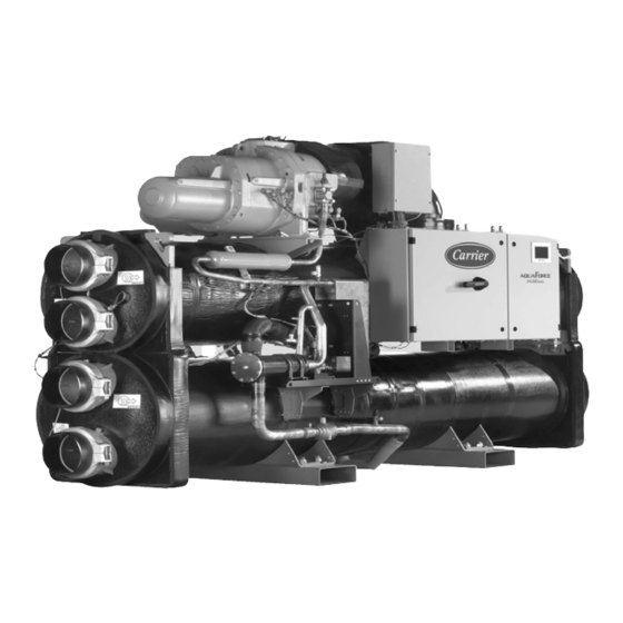
- Page 1 CO NTRO LS MAN UAL Touch Pilot Control 61XWHZE Original document...
-
Page 2: Table Of Contents
5.2 - Opening the web interface ............................. 13 5.3 - Web browser settings .............................. 13 5.4 - Technical documentation............................13 6 - TOUCH PILOT CONTROL: DETAILED MENU STRUCTURE ..............14 6.1 - Main menu ................................14 6.2 - . C onfiguration.menu ..............................19 6.3 - Alarm menu ................................ - Page 3 7.14 - Head pressure control............................27 7.15 - . M aster/Slave.assembly ............................28 7.16 - Energy Management Module (EMM) ........................ 28 7.17 - Schedule setting ..............................28 7.18 - Trending .................................. 29 8 - DIAGNOSTICS ................................ 30 8.1 - Control diagnostics..............................30 8.2 - .
- Page 4 The.goal.of.this.manual.is.to.give.a.broad.overview.of.the.main. In this manual, the refrigerant circuits are called circuit A and circuit B. functions of the Touch Pilot control system used to control and monitor the operation of 61XWHZE high condensing The following abbreviations are used frequently: single-circuit and dual-circuit heat pumps.
-
Page 5: Safety Considerations
2.1 - Control system Installation,. start-up. and. servicing. of. equipment. can. be. The Touch Pilot system controls the start-up of the compressors hazardous if certain factors particular to the installation are needed to maintain the desired heat exchanger entering and not considered: operating pressures, presence of electrical leaving.water.temperature.. -
Page 6: Hardware Description
Two types of electronic sensors (high and low pressure) are The unit is equipped with the Touch Pilot user interface used. to. measure. various. pressures. in. each. circuit..These. (5-inch colour LCD touch screen). -
Page 7: Actuators
Motor temperature sensor 3.8.2 - Volt-free contact (on/off and cooling/heating) This sensor is used to control the motor temperature of each On/off contacts and cooling/heating contacts are as follows: compressor. Cooling Heating Temperature setpoint reset sensor (EMM) On/Off contact open closed closed This 4-20 mA space temperature sensor can be installed... -
Page 8: Touch Pilot User Interface
4 - TOUCH PILOT USER INTERFACE 4.1 - General description Touch Pilot includes the 5 in. touch screen allowing for easy system control. It is recommended to use a pen for the navigation.via.the.touch.screen.. Navigation.through.the.Touch.Pilot.control.is.either.using. the touch screen interface or by connecting to the web interface..The. -
Page 9: Menu Structure
4.3 - Menu structure Home Main Menu Log in / Log out Start / Stop Alarm Menu Alarm Menu Main menu Pressures General Parameters Temperatures Pump Status Inputs Status Outputs Status Setpoint Table Run Times Modes Configuration Menu Trendings Configuration menu User Configuration General Configuration Pump Configuration... -
Page 10: Welcome Screen
4.4 - Welcome screen Information message box The.Welcome.screen.is.the.first.screen.shown.after.starting. The information displayed in the status bar at the bottom of the user interface. It displays the application name as well as the.screen.includes.relevant.messages.regarding.the.current. the.current.software.version.number. user action. All screens presented further in this manual may display the following messages: MESSAGE STATUS... -
Page 11: Display Settings
Your changes will be saved. The control system allows users to add new languages to the control. To learn more about language customization, please contact.your.local.Carrier.service.representative. 4.7.4 - System of measurement The control offers the possibility of selecting the system of 4. -
Page 12: Main Menu
4.8 - Main menu 4.9 - Configuration menu The. Main. menu. provides. access. to. the. main. control. The.Configuration.menu.gives.access.to.a.number.of.user- parameters, including general parameters, inputs and outputs modifiable.parameters.such.as.pump.configuration,.schedule. status, etc. menu, etc. • To access the menu, press the Main menu button located in the upper-left part of the Synoptic screen. -
Page 13: Web Connection
5.2 - Opening the web interface To access the Touch Pilot control, enter the IP address of the unit in the address bar of the web browser. Technical documentation includes the following documents: •... -
Page 14: Touch Pilot Control: Detailed Menu Structure
6 - TOUCH PILOT CONTROL: DETAILED MENU STRUCTURE 6.1 - Main menu Icon Displayed text* Description Associated table General Parameters General parameters GENUNIT Temperatures Temperatures TEMP Pressures Pressures PRESSURE Inputs Status Inputs status INPUTS Outputs Status Outputs status OUTPUTS Pump Status... - Page 15 General Parameters Menu – GENUNIT (continued) Name Status Unit Displayed text* Description SP_OCC no/yes Setpoint Occupied? Setpoint occupancy status: no = unoccupied yes = occupied CAP_T 0 to100 Percent Total Capacity Total unit capacity TOT_CURR Actual Chiller Current Actual chiller current CURR_LIM 0 to 4000 Chiller Current Limit...
- Page 16 Pressures Menu – PRESSURE Name Status Unit Displayed text* Description DP_A Discharge Pressure A Discharge pressure, circuit A SP_A Main Suction Pressure A Main suction pressure, circuit A OP_A Oil Pressure A Oil pressure, circuit A DOP_A Oil Pressure DifferenceA Oil pressure difference, circuit A ECON_P_A Economizer Pressure A...
- Page 17 Outputs Menu – OUTPUTS Name Status Unit Displayed text* Description COMP_A off/on Compressor A Compressor A status (circuit A) OIL_SL_A off/on Oil Solenoid Output A Oil solenoid output, circuit A SLID_1_A off/on Slide Valve 1 Output A Slide valve 1 output, circuit A SLID_2_A off/on Slide Valve 2 Output A...
- Page 18 Run Times Menu – RUNTIME (continued) Name Status Unit Displayed text* Description hr_cpum2 hour Cooler Pump #2 Hours Operating hours, evaporator pump 2 hr_hpum1 hour Condenser Pump #1 Hours Operating hours, condenser pump hr_hpum2 hour Condenser Pump #2 Hours Not applicable to this unit *Depends on the selected language (English by default).
-
Page 19: Configuration Menu
6.2 - Configuration menu Icon Displayed text* Description Associated table General Configuration General configuration GEN_CONF Pump Configuration Pump configuration PUMPCONF User Configuration User configuration USERCONF Reset Configuration Reset configuration RESETCFG Schedule Menu Schedule menu SCHEDULE Holiday Menu Holiday menu HOLIDAY Broadcast Menu Broadcast configuration BROCASTS... - Page 20 General Configuration Menu – GEN_CONF(continued) Name Status Default Unit Displayed text* Description ice_cnfg no/yes Ice Mode Enable Ice mode enabled al_rever no/yes Reverse Alarms Relay Alarm / Alert signals reverted No = standard operation Yes = alarm/alert/shutdown outputs are “On” even if there is no alarm/alert (alarm output unavailable) *Depends on the selected language (English by default).
- Page 21 Reset Configuration Menu – RESETCFG (continued) Name Status Default Unit Displayed text* Description Heating Heating dt_hr_no 0 to 13.9 Delta T No Reset Value Delta T, no reset value dt_hr_fu 0 to 13.9 Delta T Full Reset Value Delta T, max. reset value v_hr_no 0 to 20 Current No Reset Value...
-
Page 22: Alarm Menu
Date/Time configuration Menu – DATETIME Name Status Unit Displayed text* Description Date (DD/MM/YY) d_of_m 1 to 31 Day of month Day of the month month 1 to 12 Month of year Month year 20nn Year Year Monday-Sunday Day of Week Day of the week Time (HH:MM) hour... -
Page 23: Touch Pilot Control Operation
7 - TOUCH PILOT CONTROL OPERATION 7.1 - Start / Stop control • Remote start/stop contact status [Onoff_sw]: The unit state is determined based on a number of factors, Start/stop contact can be used to control the unit state including.its.operating.type,.active.overrides,.open.contacts,. -
Page 24: Cooling / Heating
7.3 - Cooling / Heating Depending on the current operation type (local/remote/ network),.the.active.setpoint.can.be.selected.manually.in.the. The Touch Pilot control can manage the whole range of Main menu (Heat/Cool Select, GENUNIT) in Local mode, operations ensuring the correct functioning of the air- with.the.volt-free.user.contacts.in.Remote.mode.(see.also. -
Page 25: Pumps Control
7.6 - Pumps control 7.5.2 - Reset Reset. means. the. active. setpoint. is. modified. so. that. less. The unit can control one or two water pump(s) per heat machine capacity is required. exchanger (one or two cooler pumps OR one condenser pump). 7.6.1 - Pump setting The.reset.source.can.be.provided.by.one.of.the.following: •... -
Page 26: Capacity Limitation
Night Mode Start Hour [nh_start]; Night Mode End Hour [nh_end] 00:00 7.7 - Capacity limitation Night Capacity Limit [nh_limit] The Touch Pilot control system allows for the constant control 0 to 100% of the unit capacity by setting its maximum allowable capacity. Capacity limitation is expressed in percentage, 7.9 - Current limitation... -
Page 27: Circuit Lead/Lag Selection (Multi-Circuit Units)
61XWHZE units are high condensing units for which the maximum.condenser.leaving.water.temperature.can.be.set. to 85°C. 7.14 - Head pressure control For water-cooled 61XWHZE units, condensing pressure control.is.assured.if.the.three-way.valve.option.is.selected.. The saturated condensing temperature is controlled based on. a. user-configurable. fixed. setpoint. (SETPOINT. menu).. The. three-way. valve. control. can. be. configured. only. by. Carrier.service.technicians. -
Page 28: Master/Slave Assembly
• Day of the week: Select the days when the period is NOTE: Master/slave assembly can be configured only by occupied. Carrier service technicians. • Occupancy time (“occupied from” to “occupied to”): Set occupancy hours for the selected days. 7.16 - Energy Management Module (EMM) •... -
Page 29: Trending
7.18 - Trending Each program is in unoccupied mode unless a schedule time period.is.active.. This.function.enables.to.visualise.the.operations.of.the.unit. and monitor a set of selected parameters. If.two.periods.overlap.and.are.both.active.on.the.same.day,. the occupied mode takes priority over the unoccupied period. • To access the Trendings screen, go to the Main menu and select Trendings (TRENDING). -
Page 30: Diagnostics
1. Press the Alarm button in the upper-right part of the screen. IMPORTANT: E-mail notifications can be configured only 2. Select Alarm Historic or Major Alarm Historic. by Carrier service technicians. 3. The history of alarms will be displayed. 8.6 - Alarms description The following table includes a list of alarms that might appear on the unit. - Page 31 Code Alarm description Reset type Action taken Possible cause 15018 Circuit A Condenser Subcooling Liquid Automatic, if thermistor Circuit A shuts down Defective thermistor Thermistor reading returns to normal 15019 Circuit B Condenser Subcooling Liquid As above Circuit B shuts down As above Thermistor 15021...
- Page 32 Code Alarm description Reset type Action taken Possible cause 10008 Circuit A High Superheat Manual Circuit A shuts down Pressure sensor defective, EXV blocked or lack of refrigerant 10009 Circuit B High Superheat Manual Circuit B shuts down As above 10010 Circuit C High Superheat Not applicable to this unit...
- Page 33 001: Circuit A Loss of charge date has passed; 002: Circuit B Loss of charge servicing action required; 004: Water loop size warning contact Carrier Service 005: Air exchanger cleanness warning Agency 006: Cooler pump 1 servicing required 007: Cooler pump 2 servicing required...
- Page 34 Code Alarm description Reset type Action taken Possible cause 1103 Compressor A High pressure switch Manual Unit shuts down Coil fouled, lack of protection condenser flow, condenser valve blocked, fan circuit fault, high entering air or condenser water temperature 1104 Compressor A Over current Manual Unit shuts down...
-
Page 35: Maintenance
In order to ensure the optimal operation of the equipment as.well.as.the.optimization.of.all.the.available.functionalities,. it.is.recommended.to.activate.a.Maintenance.Contract.with. your.local.Carrier.Service.Agency.. The contract will ensure your Carrier equipment is regularly inspected. by. Carrier. Service. specialists,. so. that. any. malfunction is detected and corrected quickly, and no serious damage can occur to your equipment. - Page 36 Order No. 10207,06.2017. Manufacturer: Carrier SCS, Montluel, France. Manufacturer reserves the right to change any product specifications without notice. Printed in the European Union.
Need help?
Do you have a question about the Touch Pilot and is the answer not in the manual?
Questions and answers