
Related Manuals for Carrier 30WG


Summary of Contents for Carrier 30WG
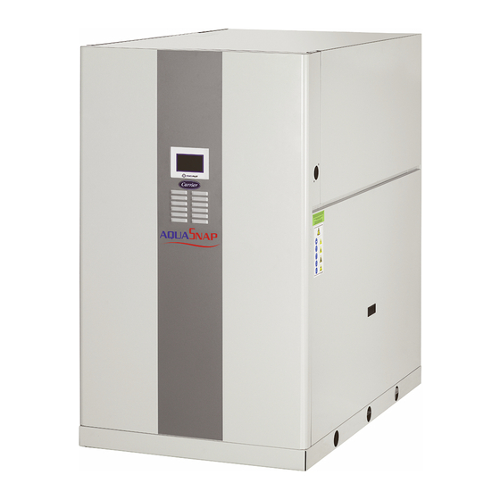
- Page 1 CO NTROLS MANUAL Touch Pilot Junior Control 30WG / 30WGA / 61WG Operation instructions Original document...
-
Page 2: Table Of Contents
CONTENTS 1 - SAFETY CONSIDERATIONS..........................5 1.1 - General description ..............................5 1.2 - Safety precautions ..............................5 2 - CONTROLLER OVERVIEW ..........................5 2.1 - Control system ................................5 2.2 - System functionalities ............................... 5 2.3 - Touch Pilot Junior components ..........................5 2.4 - Operating modes ............................... - Page 3 8.10 - Additional space heating control ........................28 8.11 - Built-in DHW and space heating control (HDC) ..................... 29 8.12 - Condensing pressure control (optional) ......................30 8.13 - Master / Slave control ............................30 9 - DIAGNOSTICS ................................ 31 9.1 - Control diagnostics..............................
- Page 4 A3. Those in circuit B are B1 and B2. • 30WG / 61WG units (cooling or heating) 30WG, 30WGA (20-140) and 61WG (20-90) units have only • 30WGA condenserless units (cooling) one circuit with one, two, or three compressors (A1, A2, A3).
-
Page 5: Safety Considerations
1.1 - General description 2.1 - Control system Installation, start-up and servicing of equipment can be 30WG / 30WGA / 61WG units come with the Touch Pilot Junior hazardous if certain factors particular to the installation are not control.that.serves.as.a.user.interface.and.a.configuration.tool. considered: operating pressures, presence of electrical for controlling the operation of the unit(s). -
Page 6: Hardware Description
(scheduled for future release). sensors are located on the suction piping of each circuit. In addition to SIOB board(s), 30WG / 30WGA / 61WG units of all sizes can be equipped with AUX1 board(s). The number Water pressure transducers... -
Page 7: Actuators
If there is a unit fault in the heating mode this output authorises diverting valve loop in case of DHW option start-up and shutdown of a boiler. 30WG/30WGA units can be.fitted.with.a.boiler.which.is.energised.only.when.requested. 3.7.2 - Volt-free contact (on/off and cooling/heating) by the controller in case of heating demand. -
Page 8: Touch Pilot Control Interface
Example: Welcome screen for 30WG Touch Pilot Junior control Touch Pilot Junior provides access to the following screens: • Welcome screen (splash screen) •... -
Page 9: Menu Structure (Basic / User Access)
4.4 - Menu structure (Basic / User access) Log in / Log out Home Main Menu Start / Stop Alarm Menu Alarm Menu Main menu Pressure General Parameters Temperature Outputs Setpoint Inputs Runtime Pump Status Heating Device Configuration Free Cooling Status Modes Configuration menu Heat/Cool Config... -
Page 10: Buttons
4.5 - Buttons HOME SCREEN Home button Main Menu button Back button Home screen displayed Main Menu displayed Go back to the previous screen Login button Start/Stop button Alarm button Basic access Unit is stopped No alarm active on the unit Blinking icon: Partial alarm (one circuit affected by the alarm) or User access... -
Page 11: Setting Up Touch Pilot Junior Control
5 - SETTING UP TOUCH PILOT JUNIOR CONTROL 5.3 - Starting / Stopping the unit 5.1 - Reading the Welcome screen With the unit in the Local off mode: The.Welcome.screen.is.the.first.screen.shown.after.starting. To display the list of operating modes and select the required the user interface. -
Page 12: Setting The Schedule
5.4 - Setting the schedule If two periods overlap and are both active on the same day, The first timer program (schedule 1) provides a means to the occupied mode takes priority over the unoccupied period. automatically switch the unit from an occupied mode to an unoccupied mode: the unit is started during occupied periods. -
Page 13: Display Settings
5.5 - Display settings 5.6 - Main menu The User Login screen allows the user to do the following: The Main menu provides access to the main control parameters, • Select the language of the controller. including general parameters, inputs and outputs status, etc. •... -
Page 14: Configuration Menu
5.7 - Configuration menu 6 - WEB CONNECTION The.Configuration.menu.gives.access.to.a.number.of.user- 6.1 - Web interface modifiable.parameters.such.as.pump.configuration,.schedule. menu, etc. The Touch Pilot Junior control can be accessed via a web browser (Internet Explorer, Mozilla Firefox, etc.). Connection is from a PC using a web browser with Java. IMPORTANT: Use firewalls and VPN for secure connection. -
Page 15: Touch Pilot Junior Interface - Detailed Menu Structure
7 - TOUCH PILOT JUNIOR INTERFACE - DETAILED MENU STRUCTURE 7.1 - Main menu Icon Displayed text* Description Associated table General Parameters General Parameters GENUNIT Temperature Temperature TEMP Pressure Pressure PRESSURE Setpoint Setpoint SETPOINT Inputs Inputs status INPUTS Outputs Outputs status OUTPUTS Pump Status Pump Status... - Page 16 General Parameters Menu – GENUNIT (continued) Point name Status Unit Displayed text* Description CHIL_S_S dsable / enable Net.: Cmd Start/Stop Unit start/stop via Network: When the unit is in Network mode, start/stop command can be forced CHIL_OCC no / yes Net.: Cmd Occupied Unit time schedule via Network: When the unit is in Network mode, the forced value can be used instead...
- Page 17 Setpoint Menu – SETPOINT Point name Status Default Unit Displayed text* Description csp1 -28.9 to 20.0 12.0 °C Cooling Setpoint 1 Cooling setpoint 1 (used during occupied periods) csp2 -28.9 to 20.0 12.0 °C Cooling Setpoint 2 Cooling setpoint 2 (used during unoccupied periods) ice_sp -28.9 to 20.0 12.0...
- Page 18 Outputs Menu – OUTPUTS (continued) Point name Status Unit Displayed text* Description LLS_B off / on Liquid Line Solenoid B Liquid line solenoid valve status, circuit B FAN_DRY Dry Cooler Fan Stages Dry cooler fan stages VFAN_DRY Variable Speed Fan DryC Variable speed fan –...
- Page 19 Heating Device Menu – HDC_STAT Point name Status Unit Displayed text* Description dhw_mode 0 to 2 Mode: Mode: 0=SHC,1=DHW, 2=moves 0 = Space Heating Control (SHC) 1 = Domestic Hot Water (DHW) 2 = Changing between SHC and DHW dhw_dem no / yes DHW Demand DHW demand...
- Page 20 Free Cooling Status Menu – FCOOL_ST (continued) Point name Status Unit Displayed text* Description fc_fanst 0 to 10 FC Fan Stage Free Cooling / Dry Cooler fan stage fc_fansp 0 to 100 FC Varifan Speed Free Cooling / Dry Cooler: Fan speed FC_HOUR 0 to 999999 hour...
-
Page 21: Configuration Menu
7.2 - Configuration menu Icon Displayed text* Description Associated table Genunit Config General configuration GENCONF Pump Configuration Pump configuration PUMPCONF Heat/Cool Config Heat/Cool configuration HCCONFIG HDC Configuration Heating Device Control configuration HDC_CONF Reset Config Reset configuration RESETCFG User Configuration User configuration USERCONF Schedule Schedule menu... - Page 22 Pump Configuration Menu – PUMPCONF (continued) Point name Status Default Unit Displayed text* Description 2 = Two Pumps Auto 2 = Two Pumps Auto (units with two pumps) 3 = Pump#1 Manual 3 = Pump#1 Manual 4 = Pump#2 Manual 4 = Pump#2 Manual clpmpdel 24 to 3000...
- Page 23 HDC Configuration Menu – HDC_CONF (continued) Point name Status Default Unit Displayed text* Description shc_min 0 to 720 SHC Minimum On Time Minimum duration of SHC shc_max -1 to 720 SHC Maximum On Time Maximum duration of SHC dhw_min 0 to 720 DHW Minimum On Time Minimum duration of DHW dhw_max...
-
Page 24: Alarms Menu
*Depends on the selected language (English by default). Control Identification Menu – CTRL_ID Status Default Displayed text* Description "xx chars" 30WG / 30WGA / 61WG Device Description Device description "xx chars" Location Description Location description: The number corresponds to the country "xx chars"... -
Page 25: Touch Pilot Junior Control Operation
• Depending on the type of water connections, 30WG/61WG units can operate in either Cooling or The table given below summarises the unit control type [ctrl_typ] Heating. The user may change the operating mode and its running status with regard to the following parameters: (cooling to heating OR heating to cooling) at any time •... -
Page 26: Control Interlock Contact
3. Set Pump Auto Rotation Delay [clpmpdel] for cooler OR Occupied Unoccupied Ice storage Cooling period period cooling setpoint 4. Set Pump Auto Rotation Delay [cdpmpdel] for condenser. 30WG/30WGA/61WG Occupied Unoccupied Pump Auto Rotation Delay [clpmpdel / cdpmpdel] Heating DHW setpoint period period 30WG/61WG... -
Page 27: Capacity Control
• By choosing the active setpoint in the General temperature reading (reset source = OAT). Parameters menu (Setpoint Select, GENUNIT). Cooling mode (30WG / 30WGA / 61WG) • Via the volt-free contacts (see section 3.7.3). Cooling control point reset is used to control the evaporator •... -
Page 28: Demand Limit
To set boiler OAT threshold During the night period the condensing point is increased to 1..Navigate.to.the.Configuration.menu. limit the number of fans operating (30WG/30WGA units 2. Select Heat/Cool Config (HCCONFIG). with dry cooler condensing control option). 3. Set Boiler OAT Threshold [boil_th]. -
Page 29: Built-In Dhw And Space Heating Control (Hdc)
• The volt-free tank request contact is closed. • Time schedule 3 is occupied (DHW mode requested) OR The Touch Pilot J. control of the 30WG/61WG includes the volt-free priority contact (DHW priority) is closed. algorithms that permit constant and automatic optimisation: Based on the operating mode the water setpoint is adjusted: •... -
Page 30: Condensing Pressure Control (Optional)
8.12 - Condensing pressure control (optional) 8.13 - Master / Slave control 30WG/61WG units can control a dry cooler to cool down The control system allows for master/slave control of two the condenser water loop while 30WGA units can control units linked by the network. -
Page 31: Diagnostics
IMPORTANT: E-mail notifications can be configured only The highlighted bell icon indicates that the unit is by Carrier service. shut down due to a detected fault. The local interface – TOUCH PILOT JUNIOR – gives the user quick access to monitor all unit operating conditions. -
Page 32: Alarms Description
9.5 - Alarms description This section includes all alarms/alerts associated with the operation of the unit as well as optional drives used to provide variable speed fans and variable speed pumps functionalities. General alarm codes The following table includes a list of alarms that might appear on the unit. - Page 33 Alarm codes (cont.) Code Description Possible cause Action taken Reset type 10008 Circuit A High Suction Superheat Pressure transducer Circuit A shuts down Manual defective, temp. sensor defective, EXV blocked or lack of refrigerant 10009 Circuit B High Suction Superheat As above Circuit B shuts down Manual...
- Page 34 Alarm codes (cont.) Code Description Possible cause Action taken Reset type 10101 Free Cooler Process Failure Dry cooler fault None Automatic, if operating conditions return to normal 15046 FreeCooler Water Loop Thermistor Failure Defective thermistor Free cooling (dry cooler) Automatic, if thermistor mode is stopped reading returns to normal 15047 FreeCooler Leaving Water Thermistor Failure...
-
Page 35: Maintenance
10 - MAINTENANCE In order to ensure the optimal operation of the equipment as well as the optimization of all the available functionalities, it is recommended to activate a Maintenance Contract with your local Manufacturer Service Agency. The contract will ensure your equipment is regularly inspected by specialists so that any malfunction is detected and corrected quickly and no serious damage can occur to your equipment. - Page 36 Order No. 10161, 09.2016. Supersedes order No.: New. Manufacturer: Carrier SCS, Montluel, France. Manufacturer reserves the right to change any product specifications without notice. Printed in the European Union.
Need help?
Do you have a question about the 30WG and is the answer not in the manual?
Questions and answers