Advertisement
Quick Links
CONTENTS
SAFETY CONSIDERATIONS . . . . . . . . . . . . . . . . . . . . . . 1
GENERAL . . . . . . . . . . . . . . . . . . . . . . . . . . . . . . . . . . . . . . . . 1
INSTALLATION . . . . . . . . . . . . . . . . . . . . . . . . . . . . . . . . 1-10
Install Harness and Make Wire
Connections . . . . . . . . . . . . . . . . . . . . . . . . . . . . . . . . . . . 5
Controls Configuration for EMM Options . . . . . . . . . 6
SAFETY CONSIDERATIONS
Installation of this accessory can be hazardous due to sys-
tem pressures, electrical components, and equipment loca-
tion (such as a roof or elevated structure).
Only trained, qualified installers and service technicians
should install, start up, and service this equipment.
When installing this accessory, observe precautions in the
literature, labels attached to the equipment, and any other
safety precautions that apply.
• Follow all safety codes.
• Wear safety glasses and work gloves.
• Use care in handling and installing this accessory.
WARNING
Electrical shock can cause personal injury and death. Shut
off all power to this equipment during installation. There
may be more than one disconnect switch. Tag all discon-
nect locations to alert others not to restore power until work
is completed.
GENERAL
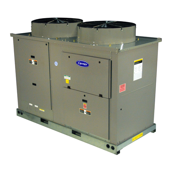
The energy management module (EMM) accessory (Fig. 1)
package is required for additional temperature reset, de-
mand limit, and remote set point features of the Com-
fortLink controls for 30MP, 30RAP and 38AP units.
Chilled water temperature reset by return water, outside air
or space temperature do NOT require the addition of this ac-
cessory. The following additional features are supported by
this accessory:
• temperature reset by 4 to 20 mA field-supplied signal.
• demand limit control via field-supplied two-step switch
input.
• demand limit control by 4 to 20 mA field-supplied
signal.
• support of unoccupied operation for ice making through
field-supplied contacts (30MP, 30RAP only).
• cooling set point control by 4 to 20 mA field-supplied
signal.
Manufacturer reserves the right to discontinue, or change at any time, specifications or designs without notice and without incurring obligations.
Catalog No. 04-53300104-01
Energy Management Module (EMM) Accessory
Installation Instructions
Part Number 38AP-900---022
Printed in U.S.A.
30MP015-045, 30RAP010-150
38APD025-130, 38APS025-065
ACCESSORY PACKAGE CONTENTS
ITEM
Energy Management Module
Harness (38APD,S025-060)
Harness (38APD,S065-130)
Harness, EMM to LVT
(30RAP, 30MP)
Harness, EMM to MBB/EXV
(Power - 30RAP, 30MP)
Harness, EMM to MBB/EXV
(Comm. - 30RAP, 30MP)
Harness, EMM to AUX
(Comm. - 30RAP, 30MP)
Screw, no. 6, 1-in. long
Wire Tie
LEGEND
EXV
— Electronic Expansion Valve
LVT
— Low Voltage Terminal
MBB
— Main Base Board
INSTALLATION
Before beginning installation of this equipment, be sure all
power to the unit is disconnected, and that tags are properly
placed to alert others. Electrical shock can cause personal
injury and death.
NOTE: Component arrangement drawings and wiring dia-
grams show available options that may not be applicable to
your unit.
1. Inspect the package contents for missing or damaged
parts. File a claim with shipping agency if parts are dam-
aged. Notify your Carrier representative if any items are
missing.
2. Open and tag all electrical disconnects.
3. Access control box:
a. Model
30RAP010-030,
38AP025-030 units: Open control box door and
remove inner cover.
b. Model 30RAP035-150 and 38AP040-130 units:
Open center control box door.
4. For 30RAP and 38AP units, loosen the four screws secur-
ing the scrolling marquee display bracket. Lift the bracket
up and slide it in the holding slots at the top of its mount-
ing bracket.
For 30MP units, carefully suspend the display bracket
from the wiring harness.
Form 30/38-11SI
Pg 1
50/60 Hz
PART NO.
QUANTITY
30GT515218
38APHLSBCE-A00
38APHLSLCE-A00
38APHSCALE-A00
38APHSCALECA10
38APHSCALECA00
38APHSCALXCA00
AL56AU130
—
WARNING
30MP015-045
11-12
Replaces: 30/38-7SI
1
1
1
1
1
1
1
1
4
and
Advertisement

Related Manuals for Carrier 30MP015-045


Summary of Contents for Carrier 30MP015-045
- Page 1 The energy management module (EMM) accessory (Fig. 1) parts. File a claim with shipping agency if parts are dam- package is required for additional temperature reset, de- aged. Notify your Carrier representative if any items are mand limit, and remote set point features of the Com- missing.
- Page 2 5. Using the no. 6 screw provided and the existing retaining 6. The board address is set through a 4-position DIP switch. clips in the control box, mount the EMM module to the All switches should be set to ON. back of the control box.
- Page 3 a30-4938 Fig. 3 — Mounting EMM — 38AP040-060 Units a30-4939 Fig. 4 — Mounting EMM — 38AP065-130 Units FB-1 TRAN CSB-A1 DISCONNECT OPTION/TB CWP1 CWP2 CWP1 CWP2 C-A1 a30-4940 Fig. 5 — Mounting EMM — 30RAP010 and 015 Units LEGEND FOR FIG. 3-5 —...
- Page 4 FB-1 TRAN CCB-2 CCB-1 FB-3 CSB-A1 CSB-A2 DISCONNECT OPTION/TB CWP2 CWP1 a30-4941 C-A1 C-A2 CWP1 CWP2 FC1/MM Fig. 6 — Mounting EMM — 30RAP018-030 Units TRAN-1 CB-1 CB-2 CB-3 CB-4 FCB-1/2/3 TRAN-2 DISCONNECT CSB-A1 CSB-A2 CSB-B1 CSB-B2 AUX LON OPTION/TB CWP1 CWP2 FC-1...
- Page 5 EQUIP UPC LON OPTION DISCONNECT OPTION CB1A/TB1A LOCATED OVER EMM CCB-3 CCB-1 CCB-2 REMOTE CONTROL CSB-A1 CSB-A2 CSB-A3 ENABLE LEGEND — Circuit Breaker — Compressor Circuit Breaker — Energy Management Module TRAN1 EQUIP — Equipment — Fuse Block — Ground —...
- Page 6 EMM connector J4. labeled AUX-J9 to AUX-J9. 2. Install the new harness 38APHSCALECA00. Install plug 30MP015-045 UNITS WITHOUT AUX BOARD — Per- labeled EXV-J4 to CXB-J4 and other end labeled EMM- form the following procedure to install the harness and J3 to EMM-J3.
- Page 7 CH11 DGS OR TO MM-A FIOP CH10 1 2 3 4 5 6 7 8 DARK = SWITCH LOCATION DEMAND LIMIT STEP 1 OR Y3 DEMAND LIMIT STEP 2 OR Y4 FIOP/ ACCESSORY DEMAND LIMIT 4-20mA TEMP RESET 4-20mA COOLING SETPOINT 4-20mA a30-4943...
- Page 8 (090-130 ONLY) PL50-1 PL50-2 PL50-3 CH11 PL50-4 DGS OR TO MM-A FIOP CH10 TO MM-B 1 2 3 4 5 6 7 8 DARK = SWITCH LOCATION DEMAND LIMIT STEP 1 OR Y3 DEMAND LIMIT STEP 2 OR Y4 FIOP/ ACCESSORY DEMAND LIMIT...
- Page 9 ICE DONE DLS STEP 1 DLS STEP 2 FIOP/ ACCESSORY DEMAND LIMIT 4-20mA TEMP RESET 4-20mA COOLING SETPOINT 4-20mA 24-V POWER CONNECTION FIOP/ACCESSORY a30-4945 A38-7212 Fig. 11 — Typical Wiring Connections (30RAP010-060 Units) Fig. 12 — Typical Wiring Connections (30RAP070-150 Units) LEGEND FOR FIG.
- Page 10 MAIN BASE AUX2 BOARD FIOP CH11 1 2 3 4 5 6 7 8 DARK = SWITCH LOCATION ICE DONE DLS STEP 1 DLS STEP 2 FIOP/ ACCESSORY DEMAND LIMIT 4-20mA TEMP RESET 4-20mA COOLING SETPOINT 4-20mA A38-7211 24-V POWER CONNECTION FIOP/ACCESSORY A38-7212 LEGEND...
- Page 12 © Carrier Corporation 2012 Manufacturer reserves the right to discontinue, or change at any time, specifications or designs without notice and without incurring obligations. Catalog No. 04-53300104-01 Printed in U.S.A. Form 30/38-11SI Pg 12 11-12 Replaces: 30/38-7SI...
Need help?
Do you have a question about the 30MP015-045 and is the answer not in the manual?
Questions and answers