Table of Contents
Advertisement
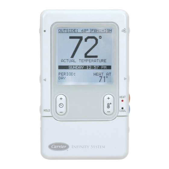
SYSTXCCUID01-- V
Infinityt Control
ZONE
HOLD
I
NFINITY
Fig. 1 - - Infinityt Control
NOTE: Read the entire instruction manual before starting the
installation.
US Patents: Carrierr U.S. Pat No. 7,243,004, Carrierr U.S. Pat No. 7,775,452
TABLE OF CONTENTS
. . . . . . . . . . . . . . . . . . . . . . . . . . . . . . . . . . .
. . . . . . . . . . . . . . . . . . . . . . . . . . . . . . . . . . . .
. . . . . . . . . . . . . . . . . . . . . . . . . . . . . . . .
. . . . . . . . . . . . . . . . . . . . . . . . . . . . . . . . . . . . .
. . . . . . . . . . . . . . . . . . . . . . . . . . . . . . . . . . . .
. . . . . . . . . . . . . . . . . . . . . . . . . . . . . . . . . . . . . .
. . . . . . . . . . . . . . . . . . . . . . . . . . . . . . .
. . . . . . . . . . . . . . . . . . . . . . . . . . . . . . . . . .
. . . . . . . . . . . . . . . . . . . . . . . . . . . . . .
Installation Instructions
HEAT
COOL
OFF
S
™
YSTEM
A04031
PAGE
. . . . . . . . . . . . . . . . . . . . . . . . .
. . . . . . . . . .
. . . . . . . . . . . . . . . . . . . .
. . . . . . . . . . . . . . . . . . . . . . . . .
. . . . . . . . . . . . . . . . . . . . . .
. . . . . . . . . . . . . . . . . . . . .
. . . . . . . . . . . . . . . . . .
SAFETY CONSIDERATIONS
Improper installation, adjustment, alteration, service, maintenance,
or use can cause explosion, fire, electrical shock, or other
conditions which may cause death, personal injury or property
damage. Consult a qualified installer, service agency or your
distributor or branch for information or assistance. The qualified
installer or agency must use factory- -authorized kits or accessories
when modifying this product. Refer to the individual instructions
packaged with the kits or accessories when installing.
Follow all safety codes. Wear safety glasses, protective clothing,
and work gloves. Have a fire extinguisher available. Read these
instructions thoroughly and follow all warnings and cautions
included in literature and attached to the unit. Consult local
building codes and the current edition of the National Electrical
Code (NEC) NFPA 70.
In Canada, refer to the current editions of the Canadian Electrical
Code CSA C22.1.
Recognize safety information. When you see this symbol
the unit and in instructions or manuals, be alert to the potential for
personal injury. Understand the signal words DANGER,
WARNING, and CAUTION. These words are used with the
safety- -alert symbol. DANGER identifies the most serious hazards,
which will result in severe personal injury or death. WARNING
signifies hazards, which could result in personal injury or death.
CAUTION is used to identify unsafe practices, which may result
in minor personal injury or product and property damage. NOTE
is used to highlight suggestions which will result in enhanced
installation, reliability, or operation.
1
1
The Infinity System consists of several intelligent communicating
2
components which includes the Infinity Control (or User
2
Interface), variable speed furnace or FE fan coil, 2- -stage AC or HP
3
and Infinity Packaged Products, which continually communicate
with each other via a four- -wire connection called the ABCD bus.
5
Commands, operating conditions, and other data are passed
7
continually between components over the ABCD bus. The result is
8
a new level of comfort, versatility, and simplicity.
All Infinity furnaces or fan coils are variable- -speed and multi stage
8
for maximum flexibility, efficiency, and comfort. They support
8
controlled ventilation, humidification, dehumidification, and air
8
quality control. Either an Infinity (communicating), or a standard
24VAC controlled outdoor unit may be used.
13
When using conventional outdoor units, the Infinity furnace or fan
14
coil provides the 24 volt signals needed to control them. Also, the
15
Infinity Network Interface Module (P/N SYSTXCCNIM01) allows
connection of a Carrier HRV or ERV without the need for a
17
separate wall control.
18
All system components are controlled through the wall mounted
Infinity Control, which replaces the conventional thermostat and
provides the homeowner with a single wall control for all features
of the system.
INTRODUCTION
on
Advertisement
Table of Contents

Related Manuals for Carrier Infinity SYSTXCCUID01-V


Summary of Contents for Carrier Infinity SYSTXCCUID01-V
-
Page 1: Table Of Contents
..... Infinity Network Interface Module (P/N SYSTXCCNIM01) allows connection of a Carrier HRV or ERV without the need for a TROUBLESHOOTING . -
Page 2: Installation And Start- -Up Overview
INSTALLATION, START- - UP OVERVIEW Remote Room Sensor and ignore its internal temperature sensor. Typically, one remote sensor is used but, multiple sensors may be This instruction covers installation of the Infinity Control only. used and averaged in some applications. Averaging requires a Physical installation instructions for the indoor and outdoor special series- -parallel wiring method with a specific number of equipment, and accessories are provided with each unit. -
Page 3: Installing Infinity Control
Recessed terminal block in wall 1 ˝ wide by 2 ˝ high Recessed Mount Interlocking Tabs (4) A03185 A03190 Fig. 3 - - Infinityt Control Fig. 7 - - Recessed Mount Assembly Surface Mount Backplate to wall Interlocking Tabs (4) A03186 A03191 Fig. - Page 4 WARNING Variable-Speed Furnace/Fan Coil User Interface ELECTRICAL OPERATION HAZARD Green Yellow Failure to follow this warning could result in personal injury, ABCD death or equipment damage. White Connection Before installing, modifying, or servicing system, the main electrical disconnect switch must be in the OFF position. 1-Spd.
-
Page 5: Initial Power- -Up
CAUTION CAUTION ELECTRICAL OPERATION HAZARD EQUIPMENT HAZARD Failure to follow this caution may result in equipment damage Failure to follow this caution may result in equipment damage. or improper operation. Do not apply 24VAC fan powered humidifier (with internal Improper wiring of the ABCD connector will cause the power supply) direct to indoor unit HUM and COM terminals. - Page 6 PURIFIER). See Table 1 and make a selection using Left or Right while in the Heat Pump Charging screens under the Heat Pump Up/Down button, then press right- -side button to continue. Checkout menu. Select “other” for non- -Carrier evaporators. Table 1 – Filter Selection Selecting Electric Heater...
-
Page 7: Quick Start
Equipment Summary 8. Press the red HEAT button to select heating humidity. 9. Adjust desired heating humidity level using either (+/- -) but- The “EQUIPMENT SUMMARY” screen will appear after ton. Accessories have been selected. This screen will give a summary of 10. -
Page 8: Install / Service Menus
INSTALL / SERVICE MENUS SETUP MENU The “INSTALL / SERVICE” menus contain a set of vital This menu has several layers, allowing modification of equipment information. This information enables the Installer or Service settings. No settings will need to be made at equipment (i.e. DIP person to view a summary of what has been installed, etc. - Page 9 Reset Factory Defaults: S EFF 325 - - fixed airflow used to achieve specified ratings - - no Program Schedule: dehumidification airflow reduction. This is nominally 325 S Yes/No to reset back to Energy Star default Time and Temp CFM/ton, but will vary if a 2- -stage outdoor unit is used. schedules.
- Page 10 Altitude S US 0 - - 2000 (default) S US 2001 - - 3000 S CA 2001 - - 4500 (for Canada only) S US 3001 - - 4000 S US 4001 - - 5000 FE Fan Coil or Variable Speed Furnace S US 5001 - - 6000 S US 6001 - - 7000 S US 7001 - - 8000...
- Page 11 Heater Size: Entered Size: S (choices dependent upon fan coil model) S (dependent on indoor unit model) This will show the heater size entered during the start- -up process. Size of the outdoor unit entered during the start- -up process. If the This value can be changed to another value (limited by the model outdoor unit is a communicating model, this value will not be number of the fan coil).
- Page 12 Lo Air Multiplier CFM/ton cooling maximum in 50 CFM increments. Adjusts the low airflow speed on non- -communicating two- -stage S Default is the cooling airflow. (350 CFM/ton) units. Choose 0.65 for units with a Bristol compressor, choose 0.80 S OFF selection does not turn off airflow if heat pump is (default) for units with a Copeland scroll compressor.
-
Page 13: Checkout Menus
With self- -identifying electric heaters, three stages of electric heat SYSTEM MAINTENANCE are available to be exercised in any combination. Non- -identifying REMIND OWNER OF heaters will only provide one stage of heat. MAINTENANCE EVERY: Enter the run time (in minutes) of each stage of heat to be exercised 12 MONTHS then press START (right- -side button). -
Page 14: Service Menus
Checkout - - System Access Module (SAM) S If static pressure cannot be accurately calculated, the display will read UNKNOWN. When this is seen, the system is adjusting to See System Access Module Installation Instructions for full details. high static pressure by cutting back blower RPM. SERVICE MENUS Service - - Heat Pump / AC Status The Service Info menu will only show the equipment installed in... -
Page 15: Operational Information
Equipment Cycle Timer (adjustable 4- -6 cycles per Run Times: S Lifetime hours of operation in heating, cooling, and how long hour) the unit has been powered. This timer prevents the start of a heating or cooling cycle until 15 S Kilowatt hours used of electric reheat for dehumidification. - Page 16 Air Filter Hybrid Heat Setup / Operation If AIR FILTER or AIR PURIFIER is installed in the indoor unit, Furnace Lockout — (in HYBRID HEAT SETUP menu) is the the system will perform a static pressure check of the system every outside temperature above which the furnace will not run except 24 hours at 1:00 p.m.
-
Page 17: Troubleshooting
TROUBLESHOOTING Please refer to the Troubleshooting Guide available on HVAC Partners for more detail. Infinity Control does not power up. 1. Recheck wiring to ABCD on all devices. 2. Make sure all colors match for every terminal. 3. Make sure power is applied to the indoor unit, and the amber LED is lit on indoor control circuit board. 4. -
Page 18: System Malfunction Screen
“IN SERVICE MODE”. The - -V Catalog No: UID01---06SI Copyright 2011 Carrier Corp. S 7310 W. Morris St. S Indianapolis, IN 46231 Printed in China Edition Date: 11/11 Manufacturer reserves the right to change, at any time, specifications and designs without notice and without obligations.
Need help?
Do you have a question about the Infinity SYSTXCCUID01-V and is the answer not in the manual?
Questions and answers