Table of Contents
Advertisement
Quick Links
DANGER!
1.
Do not attempt to adjust your Elite arm until
everything you intend to mount to the arm is
mounted.
2.
Arm must be completely horizontal (extended)
before adjusting the arm's tension. Failure to do
so will damage the arm and void the warranty.
3.
Never loosen or remove any of the shoulder bolts. Doing so
will cause the arm to immediately come apart with tremendous
force, and could cause serious injury.
4.
If equipment requiring AC power is mounted to this unit, have a
certifi ed electrician inspect the installation.
5.
Failure to install this unit according to these instructions will void
all ICW warranties. If installed incorrectly, ICW is not liable for any
damage or injury caused by the unit.
6.
Do not use power tools to adjust arm tension. MUST be adjusted
by hand.
ATTACH ARM TO MOUNT
Follow instructions on the
following pages for your style
of mount.
Ceiling Mount.............Page 2
Pole Mount ................Page 2
Wall Mount .................Page 3
Quicklink ....................Page 3
Paralink......................Page 4
ATTACH ELITE ARM COVERS
TOP COVER: Attach the long arm cover by
screwing the two 6-32 fl athead screws in the
center of the cover using a philips head
screwdriver. DO NOT USE
POWER TOOLS IN
THIS STEP!
end covers by screwing the two
10-24 fl athead screws using the 1/8 " hex key. DO
NOT USE POWER TOOLS IN THIS STEP!
Page 1 of 4
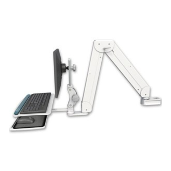
SINGLE ARM ELITE
T he Elite ar m contains high
p r e s s u r e g a s s p r i n g s . T h e
following cautions MUST be
observed to avoid serious injury.
MOUNT
END COVERS: Attach the
If you have any questions, please call 1-800-558-4435
REMOVE ELITE ARM COVERS
TOP COVER: Remove the long arm cover by
unscrewing the two 6-32 fl athead screws in the
center of the cover using a philips head
screwdriver.
RUN CORDS THROUGH ARM
Run cords through Elite end
frame and along cord channel.
ADJUST ELITE ARM RESISTANCE
SINGLE ARM ELITE INSTRUCTIONS - rev 04/21/14 pjm
MOUNT
END COVERS: Remove the
end covers by unscrewing the two
10-24 fl athead screws using the 1/8 " hex key.
Reattach black plastic
bushing around exiting
MOUNT
cords.
straight out as shown
before adjusting the
arm's resistance. Be sure all
equipment is mounted on the arm
before adjusting. Use the T-handle
provided to adjust the arms'
resistance. Do not use
power tools to adjust.
When you
begin to place
arm covers, slip
cords through
end cover cord
ports.
Extend the Elite
Advertisement
Table of Contents

Related Manuals for ICW SINGLE ARM ELITE


Summary of Contents for ICW SINGLE ARM ELITE
- Page 1 Failure to install this unit according to these instructions will void END COVERS: Remove the all ICW warranties. If installed incorrectly, ICW is not liable for any end covers by unscrewing the two damage or injury caused by the unit.
- Page 2 5mm hex key. Separate the two sections of the pole mount using the provided 5/32 hex key. Place around the pole you are mounting to and fi rmly reassemble the pole mount. Page 2 of 4 SINGLE ARM ELITE INSTRUCTIONS - rev 04/21/14 pjm...
- Page 3 Depressing of your LCD both buttons at once allows the monitor. user to position both pivots simultaneously for a total of 180 degrees of adjustment. Page 3 of 4 SINGLE ARM ELITE INSTRUCTIONS - rev 04/21/14 pjm...
- Page 4 Knob Pivot tension adjustment knob. on the back of the ball adjustment VESA. screws Page 4 of 4 SINGLE ARM ELITE INSTRUCTIONS - rev 04/21/14 pjm...
Need help?
Do you have a question about the SINGLE ARM ELITE and is the answer not in the manual?
Questions and answers