Advertisement
IF MOUNTING TO A WALL
ATTACH WALL PLATE TO WALL
IF MOUNTING TO THE
ULTRA WALL TRACK
ATTACH SLIDER TO ULTRA TRACK
Insert Slider
into Wall Track
as shown
at left and
replace the
small socket
head cap
screw and
plastic cover.
Page 1 of 2
ERGOVISION 65 INSTRUCTIONS
Locate the stud and mark
the top hole, drill 11/64
pilot hole and insert #14
screw and tighten slightly.
Using a level, mark the
lower hole and drill pilot
hole, insert #14 screw and,
with the unit level, tighten
both screws.
NOTE: ICW supplies #14
wood screws. If installing
onto metal studs, you will
need to replace with proper
metal stud fasteners.
MOUNT ULTRA TRACK TO WALL
Locate the wall stud and mark the top
hole of the Wall Track, drill 11/64 pilot
hole and insert #14 screw and tighten
slightly. Use a level, mark the lower
holes, drill pilot holes and then insert the
#14 screws.
NOTE: #14 Wood screws are supplied with unit. If
installing into metal studs, you will need to replace
these with proper metal stud fasteners
If you have any questions, please call 1-800-558-4435
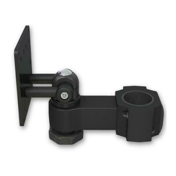
IF MOUNTING TO A POLE
ATTACH POLE CLAMP TO POLE
Once you have adjusted the
slider to the desired height,
tighten down the Track
Slider using the handle on
the slider as shown.
Once tight, make sure the
handle is positioned so that
it is pointing down as far
as possible. Pull and turn
handle to position.
ERGOVISION 65 INSTRUCTIONS - rev 04/22/14 pjm
Using the 1/4" hex key,
separate the two halves of
pole mount as shown, place
around pole at the desired
height and reassemble.
Remove
small socket
head cap
screw in the
top middle
of the Wall
Track.
Remove
plastic cover.
Advertisement
Table of Contents

Subscribe to Our Youtube Channel
Related Manuals for ICW ERGOVISION 65


Summary of Contents for ICW ERGOVISION 65
- Page 1 Once tight, make sure the small socket handle is positioned so that head cap it is pointing down as far screw and as possible. Pull and turn plastic cover. handle to position. Page 1 of 2 ERGOVISION 65 INSTRUCTIONS - rev 04/22/14 pjm...
- Page 2 3. Place cables within the channel. Do not block the holes where screws will engage in arm. 4. Replace cover and tighten screws. Cables should be able to pull through to desired position if necessary. Page 2 of 2 ERGOVISION 65 INSTRUCTIONS - rev 04/22/14 pjm...
Need help?
Do you have a question about the ERGOVISION 65 and is the answer not in the manual?
Questions and answers