Table of Contents
Advertisement
Quick Links
ICWUSA.com, Inc.
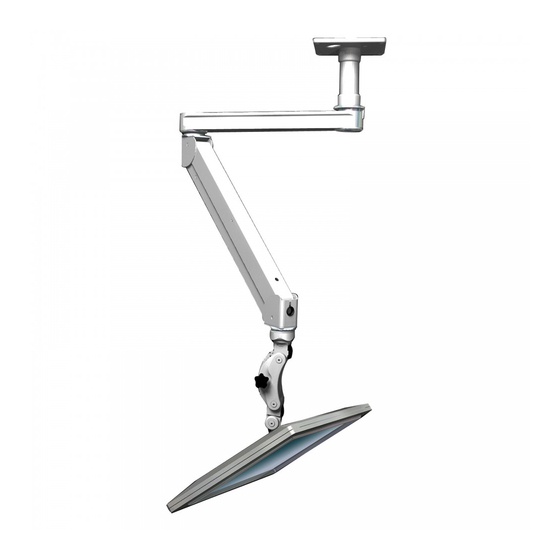
1. MOUNT SQUARE CEILING PLATE AND DROP POLE
Using four 1/4 x 2" lag bolts provided in hardware bag,
secure ceiling plate to a solid wood surface or ceiling
joist. Use square pattern or inline pattern. Be sure the
plate is level and use all four bolts.
It may be easier to pre-install the cabling through
the drop pole before installation. If you choose this
method, run a sufficient length of cable through the base
center hole or wire management port. You will require
a minimum length of 12" cabling for the XT24 drop pole
and 10" cabling for the XT12 drop pole. Then, add
required additional length on both ends. Loosen
set screw BEFORE attaching pipe.
Thread extension pipe
fully onto ceiling plate,
then tighten set screw.
Ensure drop pole
is vertically straight.
SUGGESTION:
Set inner pole at
lowest point before
moving into its
permanent position.
To avoid unnecessary
visible marks
on drop pole.
Page 1 of 3
DOUBLE ELITE CEILING MOUNT INSTALLATION
Wire management holes
Loosen the set screw
in ceiling plate before
attaching extension pipe.
If you have any questions please call Toll Free 1-800-558-4435
IMPORTANT
To avoid damaging threads,
DO NOT use power tools to assemble
or adjust the arm. Use hand tools ONLY.
MAXIMUM LOAD CAPACITY: 30 LBS (13.6 KG)
The Elite arm contains high pressure
gas springs. The following cautions
MUST be observed to avoid serious injury.
• Installation with at least two persons is recommended
for the ELP6220 series.
• Do not attempt to adjust the arm until all components
are mounted (monitor, keyboard, etc.).
• Arm must be completely horizontal (extended)
before adjusting the arm's tension. Failure to do so will
damage the arm and void the warranty.
• NEVER loosen or remove any of the shoulder
bolts. Doing so will cause the arm to immediately
come apart with tremendous force, and could cause
serious injury (see screen .
• If equipment requiring AC power is mounted to this unit,
have a certified electrician inspect the installation.
• Failure to install this unit according to these instructions
will void all ICW warranties. If installed incorrectly, ICW
is not liable for any damage or injury caused by the unit.
2. ATTACH ARM TO DROP POLE
Check that set screw
is backed out enough
to tighten. Fully thread
arm onto extension
pipe and tighten.
NOTE: There is a hole
for a spanner that can be
used to add extra leverage
for tightening the thread.
AFTER arm is firmly
attached, tighten
set screw with 5/32
hex key. Once set,
retighten set screw.
WARNING:
DO NOT loosen lower,
smaller screw without
approval from ICW.
TITAN ELITE EASY-TO-WIRE CEILING MOUNT INSTALLATION - 12/12/17
DANGER!
Set screw
Advertisement
Table of Contents

Subscribe to Our Youtube Channel
Related Manuals for ICW Elite


Summary of Contents for ICW Elite
- Page 1 NOTE: There is a hole set screw BEFORE attaching pipe. for a spanner that can be Thread extension pipe used to add extra leverage fully onto ceiling plate, for tightening the thread. then tighten set screw. Ensure drop pole AFTER arm is firmly is vertically straight. attached, tighten set screw with 5/32 Wire management holes SUGGESTION: hex key. Once set, Set inner pole at retighten set screw. lowest point before moving into its WARNING: permanent position. DO NOT loosen lower, To avoid unnecessary smaller screw without visible marks Loosen the set screw approval from ICW. on drop pole. in ceiling plate before attaching extension pipe. Page 1 of 3 TITAN ELITE EASY-TO-WIRE CEILING MOUNT INSTALLATION - 12/12/17...
- Page 2 Reattach arm covers, slip black plastic wires through bushing around end cover port. exiting wires. 8. ATTACH MONITOR VESA TO MOUNT Attach VESA to monitor using four M4 screws in the hardware bag. Mount the VESA assembly by screwing the knob through the rail into the VESA. Use the slider knob to loosen the slider to Feed the cables between the elite arms adjust the height of the monitor on the Paralink. through the center frame and into the Adjust the pivot tension of the ball by gently black channel of the second elite arm. and evenly tightening or loosening the four Repeat these steps with the remaining cables. screws on the back of the ball VESA. Page 2 of 3 TITAN ELITE EASY-TO-WIRE CEILING MOUNT INSTALLATION - 12/12/17...
- Page 3 Minimum torque values Monitor Mount • Remove long top cover and front end cover. Base Mount Arm Joint Paralink EV710 Ultra • Insert 9/16 socket wrench over nut in end frame. • From beneath arm, slightly loosen center bolt with provided hex key. Titan (T2) • Tighten set screws with hex key until foot is level, UL180 / UL182 then retighten center bolt. Check for level. Repeat MD Arm if necessary. If center bolt is not retightened, the Elite foot could come loose. • Replace arm covers, as in screens 6 and 7. Page 3 of 3 TITAN ELITE EASY-TO-WIRE CEILING MOUNT INSTALLATION - 12/12/17...
Need help?
Do you have a question about the Elite and is the answer not in the manual?
Questions and answers