Table of Contents
Advertisement
Quick Links
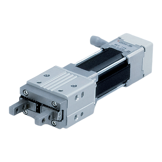
Applicable models: LEHZ(J), LEHF, LEHS
Z Type
(2 Finger Type)
●Standard
/ LEHZ Series
●With Dust Cover
/ LEHZJ Series
PRODUCT NAME
Electric Gripper
MODEL/ Series
LEH Series
<Controller>
LEC Series
Doc. no. LEHZ-OM00204
F Type
(2 Finger Type)
●Standard / LEHF Series
S Type
(3 Finger Type)
●Standard / LEHS Series
Advertisement
Table of Contents

Related Manuals for SMC Networks LEH Series


Summary of Contents for SMC Networks LEH Series
- Page 1 Doc. no. LEHZ-OM00204 PRODUCT NAME Electric Gripper MODEL/ Series LEH Series Applicable models: LEHZ(J), LEHF, LEHS Z Type F Type (2 Finger Type) (2 Finger Type) ●Standard ●Standard / LEHF Series / LEHZ Series ●With Dust Cover S Type (3 Finger Type) / LEHZJ Series ●Standard / LEHS Series...
-
Page 2: Table Of Contents
Contents Safety Instructions.................. 3 1. Procedure before operation/simple setting to use straight away... 5 1.1 Preparation ................... 5 (1) Items to be prepared........................5 (2) Actuator wiring...........................5 1.2 Controller setting software version..........6 (1) Installation of software ......................6 (2) Startup of software........................6 (3) JOG Drive ...........................6 (4) TEST Drive / Step No.0 →... - Page 3 Example of step data entry (1) .....................31 Example of step data entry (2) .....................32 Example of step data entry (3) .....................33 Operating procedure and input / output signals for each operation........34 5.4 Parameter setting............... 36 Initial setting for the basic parameters..................36 Initial setting for the ORIG parameters..................38 6.
-
Page 4: Safety Instructions
LEH Series / Electric Gripper Safety Instructions These safety instructions are intended to prevent hazardous situations and/or equipment damage. These instructions indicate the level of potential hazard with the labels of “Caution,” “Warning” or “Danger.” They are all important notes for safety and must be followed in addition to International Standards (ISO/IEC), Japan Industrial Standards (JIS)*1) and other safety regulations*2). - Page 5 LEH Series / Electric Gripper Safety Instructions Caution The product is provided for use in manufacturing industries. The product herein described is basically provided for peaceful use in manufacturing industries. If considering using the product in other industries, consult SMC beforehand and exchange specifications or a contract if necessary.
-
Page 6: Procedure Before Operation/Simple Setting To Use Straight Away
1. Procedure before operation/simple setting to use straight away The controller is already set with the data of the actuator. With the simple setting “easy mode”, it can be operated and running parameters can be changed easily. 1.1 Preparation (1) Items to be prepared Please check what is written on the label, and the quantity of accessories, to confirm that it is the product that was ordered. -
Page 7: Controller Setting Software Version
1.2 Controller setting software version (1) Installation of software With the controller setting software CD-ROM, install the communication unit software, following the “Software Installation procedure” (PDF) (2) Startup of software After turning on the controller power supply, start up the ACT Controller. Select “Easy Mode”... -
Page 8: Test Drive / Step No.0 → No.1 → No.0
(4) TEST Drive / Step No.0 → No.1 → No.0・・・ a. Driving preparation : Servo On → Return to ORIG / Refer to 3.JOG Drive. b.TEST Drive “Step No.0” Operation Procedure 2: → Operation Procedure 1: Select “Drive” Select “Step No.0” You can select anywhere in the row “Step No.1”... -
Page 9: Teaching Box
1.3 Teaching box (1) Name (2) JOG key (3)SET key (4) Up and down, right and left key (5)MENU key (1) Number key (2) JOG Drive データ テスト モニタ EXT Inp OFF:YES Operates by (2) JOG key DATA TEST MONITOR Press the (3)SET key JOG+: Open ↓... -
Page 10: Test Drive / Step No.0 → No.1 → No.0
(4) Step data change “Step No.0” / Positioning operation データ テスト モニタ Screen to stop at Change of positioning DATA MONITOR TEST 24mm position stop position Posn 24 mm → 20mm アラーム ジョグ 設定 Step ALARM Step SETTING Step No. Step No. -
Page 11: Electric Gripper/Lehz Series
2. Electric Gripper/LEHZ Series 2.1 LEHZ Series / Standard 2.1.1 Specification Model LEHZ10 LEHZ16 LEHZ20 LEHZ25 LEHZ32 LEHZ40 Stroke/both sides (mm) Gripping force Basic 6 to 14 16 to 40 to 130 to 210 Note 1) 40 to 100%(N) Compact 2 to 6 3 to 8 11 to 28... -
Page 12: How To Order
2.1.2 How to Order LEHZ 10 □ - □ □ - □ Controller option Size fingers Screw mounting type Screw mounting type Motor size DIN rail mounting type DIN rail mounting type Basic Basic I/O cable length(m) Without cable Without cable Compact Compact Note) -
Page 13: Construction
2.1.3 Construction Manual override Parts list Part Material Remarks Body Aluminum alloy Anodized Motor plate Aluminum alloy Anodized Guide ring Aluminum alloy Heat treated, Slide nut Stainless steel Specially treated Heat treated, Slide bolt Stainless steel Specially treated Needle roller High carbon chromium bearing steel Needle roller High carbon chromium bearing steel... -
Page 14: Lehzj Series / With Dust Cover
2.2 LEHZJ Series / With Dust Cover 2.2.1 Specification Model LEHZJ10 LEHZJ16 LEHZJ20 LEHZJ25 Stroke/both sides (mm) Basic 6 to 14 (40 to 100%) 16 to 40 (40 to 100%) Gripping force 3 to 6 4 to 8 Note 1) Compact 11 to 28 (40 to 100%) (50 to 100%) -
Page 15: How To Order
2.2.2 How to Order □ - LEHZ □ - □ □ Controller option With Dust Cover Screw mounting type Screw mounting type Size DIN rail mounting type DIN rail mounting type I/O cable length(m) Motor size Without cable Without cable Basic Basic Compact... -
Page 16: Construction
2.2.3 Construction Manual override 11 13 3 2 5 1 4 7 6 9 8 12 10 Parts list Part Material Remarks Body Aluminum alloy Anodized Motor plate Aluminum alloy Anodized Guide ring Aluminum alloy Heat treated, Slide nut Stainless steel Specially treated Heat treated, Slide bolt... -
Page 17: Protection Seal To Prevent Ingress Of Dust
2.2.4 Protection seal to prevent ingress of dust When using the LEHZJ series, please affix the "protection seal to prevent ingress of dust" provided. Otherwise machining chips and fine particles may get into the product from the outside, leading to operation failure. -
Page 18: Electric Gripper/Lehf Series
3. Electric Gripper/LEHF Series 3.1 Specification Model LEHF10 LEHF20 LEHF32 LEHF40 Stroke/both sides Basic long st. (mm) Note 1) 3 to 7 11 to 28 48 to 120 72 to 180 Gripping force 40 to 100%(N) Opening/closing speed (mm/s) 5 to 80 5 to 100 Note 2) Gripping speed (mm/s) -
Page 19: How To Order
3.2 How to Order LEHF 10 K □ - - □ Controller option Size 2 fingers Screw mounting type Screw mounting type DIN rail mounting type DIN rail mounting type I/O cable length(m) Without cable Without cable Lead Basic Basic Stroke(mm) Controller Stroke to both sides... -
Page 20: Construction
3.3 Construction Manual override on both sides Parts list Part Material Remarks Body Aluminum alloy Anodized Side plate A Aluminum alloy Anodized Side plate B Aluminum alloy Anodized Heat treated, Slide shaft Stainless steel Specially treated Slide bush Stainless steel Heat treated, Slide nut Stainless steel... -
Page 21: Electric Gripper/Lehs Series
4. Electric Gripper/LEHS Series 4.1 Specification Model LEHS10 LEHS20 LEHS32 LEHS40 Stroke/dia.(mm) Basic 2.2 to 5.5 9 to 22 36 to 90 52 to 130 Gripping force Note 1) 40 to 100%(N) Compact 1.4 to 3.5 7 to 17 Opening/closing speed (mm/s) 5 to 70 5 to 80 5 to 100... -
Page 22: How To Order
4.2 How to Order LEHS 10 □ - □ - □ Controller option Size 3 fingers Screw mounting type Screw mounting type DIN rail mounting type DIN rail mounting type I/O cable length(m) Without cable Without cable Motor size Basic Basic Compact Compact... -
Page 23: Construction
4.3 Construction Manual override Parts list Part Material Remarks Body Aluminum alloy Anodized Motor plate Aluminum alloy Anodized Guide ring Aluminum alloy Heat treated, Slide cam Stainless steel Specially treated Heat treated, Slide bolt Stainless steel Specially treated Heat treated, Finger Carbon steel Specially treated... -
Page 24: Product Outline
5. Product Outline 5.1 System construction ●I/O cable ● Electric gripper Part No:LEC-CN5-∗ Motor cable ●Controller Power supply DC24V To CN5 Option Communication To CN4 cable To CN4 Controller setting To CN3 software Conversion ●Actuator cable unit (Robotic type cable) モニ... -
Page 25: Setting Function
5.2 Setting Function Refer to the operation manual of the cotroller (LEC series) for details of the setting function. Easy Mode for simple setting >Select “Easy mode” for instant operation Controller setting software Setting and operation, such as the step data setting, test drive and JOG / fixed-distance moving, can be performed on the same page. - Page 26 Normal mode for the detailed setting >Select “Normal mode” if the detailed setting are necessary. Step data can be set in detail. Parameters can be set. Signals and terminal condition can be monitored. JOG and fixed distance movement, return to origin position, test operation and testing of compulsory output can be done.
- Page 27 Controlled items PC: Controller setting software TB: Teaching box Normal Easy Mode Function Content mode PC/TB Movement method Can be selected of absolute/relative position move Can be set in units of 1mm/s. It is the speed between the fingers. Speed Can be set in units of 0.01mm.
-
Page 28: Step Data Setting
5.3 Step data setting Refer to the operation manual of the controller (LEC series) for details. This operation manual specifies the electric gripper, if an actuator other than the electric gripper is used, refer to the operation manual of each type of actuator and controller (LEC series) regarding the description of step data. - Page 29 <Items and set values in positioning operation> Step No. 0: Positioning operation 【◎】 Need to be set ・ 【○】Need to be adjusted as required 【X】 Not used. Items don't need to be changed in positioning operation. a <◎ Movement MOD> When the absolute position is required, set Absolute When the relative position is required, set Relative ⇒...
-
Page 30: Gripping Operation (Pushing Operation)
Gripping operation (Pushing operation) The fingers move to the target position and hold a work piece with the set thrust force.The figure shows setting items and operation.The setting items and values are described below. < Confirmation of reaching the target value during the gripping operation> The target position reached signal INP (in position) is generated when the target thrust force (Trigger LV) is achieved. - Page 31 <Items and setting values of gripping operation> Step no. 1: Gripping operation 【◎】 Need to be set ・ 【○】Need to be adjusted as required a <◎ Movement MOD> When the absolute position is required, set Absolute When the relative position is required, set Relative ⇒...
-
Page 32: Example Of Step Data Entry (1)
Example of step data entry (1) data data Gripping - 31 -... -
Page 33: Example Of Step Data Entry (2)
Example of step data entry (2) data Gripping Pushing Gripping force Caution (11) on p. 53 /See 8.3 Gripping: Not - 32 -... -
Page 34: Example Of Step Data Entry (3)
Example of step data entry (3) < Gripping operation explained > The gripping action is different and dependent upon the starting position and direction. Confirm the position where the gripping operation starts. Example) Condition 1) In case the gripping operation is Step no. -
Page 35: Operating Procedure And Input / Output Signals For Each Operation
Operating procedure and input / output signals for each operation. The input / output signal and the operation description for operating this electric actuator are as follows. 1) Signals along with the operation procedures In case the operation order is 1. - Page 36 2) Signals when stopped: In the event when “EMG” is used / See 8.3 Caution (9) on p. 52 The operating sequence is 1. “Stop” 2. Release the “Stop” Output signal for the input Procedure Input signal Operation description signal Power to the motor is cut by the *ESTOP[ EMG: Not energizing...
-
Page 37: Parameter Setting
5.4 Parameter setting Initial setting for the basic parameters Refer to the controller’s (LEC series) operation manual for detail. As the “basic parameter” is unique data of each actuator, if an actuator other than the electric gripper is used, refer to the operation manual of each actuator and the controller’s (LEC series) operation manual for the basic parameter. - Page 38 2) Origin offset The origin offset means the value of the origin. (Origin offset = origin) The moving amount in the opposite direction is set at 1 mm (not changeable), so add/ subtract 1 mm when the origin offset parameter is changed. When the parameter is changed, the current position is changed.
-
Page 39: Initial Setting For The Orig Parameters
Initial setting for the ORIG parameters Refer to the controller’s (LEC series) operation manual for detail. As the “ORIG parameter” is unique data of each actuator, if an actuator other than the electric gripper is used, refer to the operation manual of each actuator and the controller’s (LEC series) operation manual for the for the “ORIG parameters”... -
Page 40: Wiring Of Cables / Common Precautions
6. Wiring of cables / Common precautions Warning Adjusting, mounting or wiring change should never be done before disconnecting the power supply to the product. Electrical shock, malfunction and damage can result. Do not disassemble the cables. Use only specified cables. Do not connect or disconnect the wires, cables and connectors when the power is turned on. -
Page 41: Electric Actuators / Common Precautions
7. Electric actuators / Common precautions 7.1 Design and selection Warning 1. Be sure to read the operation manual (this manual and the one for the controller: LEC series). Handling or usage/operation other than that specified in the Operation Manual may lead to breakage and operation failure of the product. -
Page 42: Mounting
Returning to origin cannot be done during the operation. It cannot be done during positioning operation, pushing operation and pushing. 7.2 Mounting Warning 1. Install and operate the product only after reading the Operation Manual carefully and understanding its contents. Keep the manual in a safe place future reference. 2. - Page 43 When installing, adjusting, inspecting or performing maintenance on the product, controller and related equipment, be sure to turn off the power supply to each of them. Then, lock it so that no one other than the person working can turn the power on, or implement measures such as a safety plug.
-
Page 44: Operating Environment
7.4 Operating environment Warning 1. Avoid use in the following environments. a. Locations where a large amount of dusts and cutting chips are airborne. b. Locations where the ambient temperature is outside the range (refer to specifications). c. Locations where the ambient humidity is outside the range (refer to specifications). d. -
Page 45: Electric Gripper/Specific Product Precautions
2. Removal of product When equipment is serviced, first confirm that measures are in place to prevent dropping of work pieces and run-away of equipment, etc, and then cut the power supply to the system. When machinery is restarted, check that operation is normal with actuators in the proper positions. [Lubrication] Caution 1. - Page 46 Finger Attachment Gripping spase Gripping spas 逃げ部 逃げ部 Needle shaped work piece 薄板ワーク Needle shaped work piece 針状ワーク Select the model that allows for gripping force in relation to the weight of a work piece, as appropriate. The selection of inappropriate model can cause dropping of a work piece. Gripping force should be from 10 to 20 times (LEHZ(J),LEHF) or 7 to 13 times (LEHS) of the weight of the object to be conveyed.
-
Page 47: Mounting
8.2 Mounting Warning Do not drop or hit the gripper when mounting to avoid scratches and dents. Even slight deformation can cause the deterioration of accuracy and operation failure. Tighten the attachment mounting screws to the specified torque. Tightening to a torque over the specified range can cause operation failure, and insufficient torque can cause displacing or dropping of the attachment. - Page 48 < LEHZ Mounting > Mounting by screws to Max. Max. thread the side of the body tightening Part no. Bolt depth L[mm] torque Manual [Nm] override LEHZ(J)10(L)K2-4 M3×0.5 LEHZ(J)16(L)K2-6 M4×0.7 LEHZ(J)20(L)K2-10 M5×0.8 LEHZ(J)25(L)K2-14 M6×1 LEHZ32K2-22 M6×1 Finger LEHZ40K2-30 M8×1.25 12.0 Attachment Mounting by screws to the mounting plate...
- Page 49 < LEHF Mounting> Max. Mounting by screws to the Max. thread tightening side of the body Part no. Bolt depth L[mm] torque Manual [Nm] override on LEHF10K2-* M4×0.7 both sides LEHF20K2-* M5×0.8 LEHF32K2-* M6×1 LEHF40K2-* M6×1 Finger Attachment Mounting by Max.
- Page 50 Tighten the product mounting screws to the specified torque. Tightening to a torque over the specified range can cause operation failure, and insufficient torque can cause displacing or dropping of the attachment. When fixing the attachment to the finger, avoid applying excessive torque to the finger. Play or deteriorated accuracy can result.
-
Page 51: Handling
When mounting a work piece, align it with the product carefully to prevent excessive force to the finger. In particular, during a a trial run, operate the product manually or at a low speed and check that the safety is assured without impact. O : Aligned X : Not aligned ○心が合っている... - Page 52 Do not change the setting of the electric power saving mode. When gripping operation is continued, the heat generated by the motor can cause operation failure. This is due to the self-lock mechanism in the lead screw, which makes the product keep the gripping force.
- Page 53 LEHF series Pushing speed [mm/sec] Pushing force 21 to 30 50% to 100% 5 to 20 40% to 100% LEHS series Motor size Pushing speed [mm/sec] Pushing force 41 to 50 50% to 100% Standard 5 to 40 40% to 100% 31 to 50 80% to 100% Compact...
-
Page 54: Maintenance
3) “M24V (motor driving power supply)” of the CN1 of the controller is shut off. a) There will be no change in output conditions due to stop. b) How to restart operation In this situation, operation can be restarted after stop is released. It is not necessary to remove a work piece beforehand because a motor magnetic pole detective operation will not occur. -
Page 55: Troubleshooting
9. Troubleshooting Alarms below are abstract of representative examples. For other alarms, see operation manual of controller. Phenomenon Cause Countermeasure Fail to operate 1) The cable is not connected Confirm that the cable is / Initial stage or has been disconnected. connected correctly. - Page 56 Phenomenon Cause Countermeasure Operation not completed 1) The lead screw had galling due Operate within the specified range /See 2.1.1 Specifications on p.10 for LEHZ / Operation continue to excessive external force /See 2.2.1 Specifications on p.13 for LEHZJ (including vibration) or impact. /See 3.1 Specifications on p.17 for LEHF Alarm for “Posn failed /See 4.1 Specifications on p.20 for LEHS...
- Page 57 Phenomenon Cause Countermeasure Alarm for “Pushing ALM 1) For the Gripping operation, the Check the step data. Caution /code: 1-096” is generated. position, target start-pushing /See 8.3 (11) on p.53 ↓ position, is not set correctly. <Procedure of restart> Controller version /SV1.0 or later 1.
- Page 58 Phenomenon Cause Countermeasure Alarm for “ Err overflow 1) The lead screw had galling due Operate within the specified range /See 2.1.1 Specifications on p.10 for LEHZ /code: 1-196” is generated. to excessive external force /See 2.2.1 Specifications on p.13 for LEHZJ ↓...
- Page 59 Phenomenon Cause Countermeasure Operation not completed 1) Command invalid Check if the step data is valid / During operation (unregistered) step data. (registered). (Not always, but may happen 2) Different input signal to the Add an interval of 30msec or more occasionally) expected step number is between the input signals.
- Page 60 Phenomenon Cause Countermeasure "Output signal" unstable the 1) "INP output signal" turns "ON" Set the "Pushing force" and the "INP output signal" turns "ON" because the actual thrust force "TriggerLV" within the specified before gripping the work piece. exceeds "TriggerLV". range for the "Pushing speed"...
- Page 61 Revision history 4-14-1, Sotokanda, Chiyoda-ku, Tokyo 101-0021 JAPAN Tel: + 81 3 5207 8249 Fax: +81 3 5298 5362 http://www.smcworld.com Note: Specifications are subject to change without prior notice and any obligation on the part of the manufacturer. © 2010 SMC Corporation All Rights Reserved - 60 -...
Need help?
Do you have a question about the LEH Series and is the answer not in the manual?
Questions and answers