
Related Manuals for SMC Networks LEFS Series


Summary of Contents for SMC Networks LEFS Series
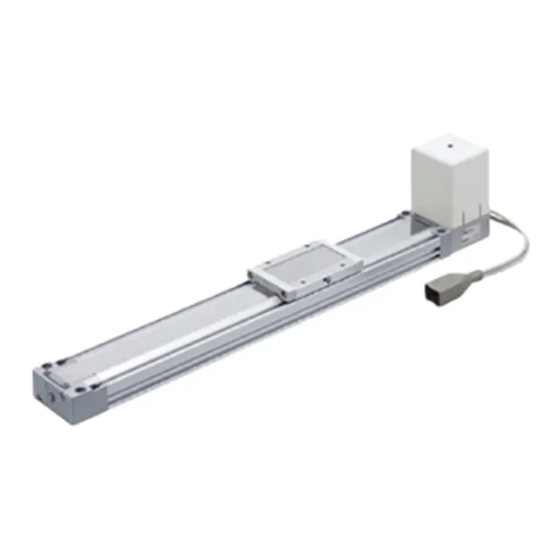
- Page 1 Doc. no. LEF-OM00410 PRODUCT NAME Electric Actuator / Slider Type 《AC Servo Motor》 MODEL / Series / Product Number MODEL : LEFS, LEFB Series : LEF...
-
Page 2: Table Of Contents
1.3 Gain tuning ................7 1.3.1 Procedure ................7 1.3.2 The recommended the parameter for each driver ....8 2. Slider type LEFS series ............... 19 2.1 Specification ................19 2.2 How to Order ................20 2.3 Construction ................21 3. -
Page 3: Safety Instructions
Safety Instructions These safety instructions are intended to prevent hazardous situations and/or equipment damage. These instructions indicate the level of potential hazard with the labels of “Caution,” “Warning” or “Danger.” They are all important notes for safety and must be followed in addition to International Standards (ISO/IEC) , and other safety regulations. - Page 4 Safety Instructions Caution The product is provided for use in manufacturing industries. The product herein described is basically provided for peaceful use in manufacturing industries. If considering using the product in other industries, consult SMC beforehand and exchange specifications or a contract if necessary. If anything is unclear, contact your nearest sales branch.
-
Page 5: Procedure Before Operation
1. Procedure before operation 1.1 Preparation (1) Items to be prepared Please check on the label, and the quantity of accessories, to confirm that it is the product that was ordered. Table 1. Componets Part name Electric Actuator / LEF Series Driver / LECS Series 1(in case with driver) Motor cable... - Page 6 LECSC, LECSC-T(CC-Link) Driver Motor cable Lock cable DC24V Encoder cable Host controller, Electric Actuator I/O Connector LECSS(SSCNET III), LECSS-T(SSCNET III/H) Driver Motor cable Lock cable DC24V Encoder cable Host controller, Electric Actuator I/O Connector - 5 -...
-
Page 7: Startup
1.2 Startup When switching the power on for the first time, follow the startup procedure below. Settings may be required for LEFB25S, refer to section 1.3.2. Refer to the “Driver operation manual” for wiring method and detailed procedure. Confirm that the cables to the driver and the actuator are - - - Wiring check connected correctly. -
Page 8: Gain Tuning
1.3 Gain tuning 1.3.1 Procedure Here are the steps for basic gain tuning. Refer to the “Driver operation manual” for details and for tuning methods other than shown below. ●For LECSA(Pulse input / Positioning) A. One-touch tuning During motor driving, push “AUTO” button on the front of the driver for three seconds. When display panel becomes “... -
Page 9: The Recommended The Parameter For Each Driver
1.3.2 The recommended the parameter for each driver The recommended the parameter for each driver. Please change the parameter values by use of the customer. Please refer to the manual of the driver for more details. 【LECSA】 LEFS25 LEFS32 LEFS40 Series Lead symbol Lead... - Page 10 【LECSA】 LEFB25 LEFB25U LEFB32 LEFB32U LEFB40 LEFB40U Series Lead symbol Lead Para Initial Parameter Recommended value value Number of command PA05 input pulses per revolution *3 Electronic gear PA06 100(Positioning mode: 10) numerator *3 Electronic gear PA07 denominator *3 Feel length 0000(Less than stroke 1000)/ PE02 0000...
- Page 11 【LECSB】 LEFS25 LEFS32 LEFS40 Series Lead symbol Lead Para. Initial Parameter Recommended value value Number of command input pulses per PA05 revolution *3 Electronic gear PA06 32768 numerator *3 Electronic gear PA07 denominator *3 Regenerative option PA02 0000 0000(Non) / 0002(LEC-MR-RB-032) Rotation direction PA14 1(+:Counter motors side)
- Page 12 【LECSC】 LEFS25 LEFS32 LEFS40 Lead symbol Series Lead Para. Initial Parameter Recommended value value Electronic gear PA06 32768 numerator *3 Electronic gear PA07 2500 1500 3000 2000 1000 3750 2500 1250 denominator *3 Feel length 0000(Less than stroke 1000)/ multiplication (STM) PA05 0000 0001(Stroke 1000 or more)
- Page 13 【LECSC】 LEFB25 LEFB25U LEFB32 LEFB32U LEFB40 LEFB40U Lead symbol Series Lead Para. Initial Parameter Recommended value value Electronic gear PA06 32768 numerator *3 Electronic gear PA07 6750 denominator *3 Feel length 0000(Less than stroke 1000)/ multiplication (STM) PA05 0000 0001(Stroke 1000 or more) (Multiplier) Home position return PC02...
- Page 14 【LECSS】 LEFS25 LEFS32 LEFS40 Lead symbol Series Lead Para. Initial Parameter Recommended value value Regenerative option PA02 0000 0000(Non) / 0002(LEC-MR-RB-032) Rotation direction PA14 1(+:Counter motors side) selection Adaptive tuning mode PB01 0000 0000 Load to motor inertia PB06 moment ratio Machine resonance PB13 4500...
- Page 15 【LECSB-T】 LEFS25 LEFS32 LEFS40 Series Lead symbol Lead Initial Para Parameter *1,*2 Recommended Value value Number of command input pulses per PA05 10000 10000 revolution *3. Electronic gear numerator *3. PA06 262144 (Position control mode) 2000 1200 2400 1600 3000 2000 1000 Electronic gear denominator *3.
- Page 16 【LECSB-T】 LEFB25 LEFB25U LEFB32 LEFB32U LEFB40 LEFB40U Series Lead symbol Lead Initial Para Parameter *1,*2 Recommended value value Number of command input PA05 10000 10000 pulses per revolution *3. Electronic gear numerator *3. PA06 262144 (Position control mode) 5400 Electronic gear denominator *3. PA07 (Positioning mode) 54000...
- Page 17 【LECSC-T】 LEFS25 LEFS32 LEFS40 Lead symbol Series Lead Para. Initial Parameter *1,*2 Recommended value value Electronic gear PA06 32768 numerator *3 Electronic gear PA07 2500 1500 3000 2000 1000 3750 2500 1250 denominator *3 Feel length multiplication (STM) PA05 0000(Less than stroke 1000)/ 0001(Stroke 1000 or more) 0000 (Multiplier) Home position return...
- Page 18 【LECSC-T】 LEFB25 LEFB25U LEFB32 LEFB32U LEFB40 LEFB40U Lead symbol Series Lead Para. Initial Parameter *1,*2 Recommended value value Electronic gear PA06 32768 numerator *3 Electronic gear PA07 6750 denominator *3 Feel length multiplication (STM) PA05 0000(Less than stroke 1000)/ 0001(Stroke 1000 or more) 0000 (Multiplier) Home position return...
- Page 19 【LECSS-T】 LEFS25 LEFS32 LEFS40 Series Lead symbol Lead Para Initial Parameter Recommended value value 0000(Non)/0002(LEC-MR-RB-032) Regenerative option PA02 0000 0003(LEC-MR-RB-12) Rotation direction PA14 1(+:Counter motors side) selection 【LECSS-T】 LEFB25 LEFB25U LEFB32 LEFB32U LEFB40 LEFB40U Series Lead symbol Lead Para Initial Parameter Recommended value value...
-
Page 20: Slider Type Lefs Series
2. Slider type LEFS series 2.1 Specification LEFS25,32,40 AC servo motor (100W / 200W/400W/) Model LEFS25 LEFS32 LEFS40 Note 1) Stroke [mm] 50~800 50~1000 150~1200 Work load [kg] Note 2) Work load [kg] Vertical ~ 400 1500 1500 1000 1500 1000 401 ~... -
Page 21: How To Order
2.2 How to Order - 20 -... -
Page 22: Construction
2.3 Construction LEFS <AC servo motor / In-line mouting> Dust seal band type: Auto switch mounting bracket Seal band holder roller specification Description Material Note 番号 部品名 材質 備考 Body Aluminum alloy Anodized Motor Rail guide Grommet Ball screw shaft Band holder Stainless steel Ball screw nut... - Page 23 LEFS <AC servo motor / Parallel mounting> Auto switch mounting bracket Dust seal band type: Seal band holder roller specification Parts list Description Material Note Description Material Note Body Aluminum alloy Anodized Table spacer Aluminum alloy Only LEFS32 Rail guide Motor Ball screw shaft Motor adaptor...
-
Page 24: Slider Type Lefb Series
3. Slider type LEFB series 3.1 Specification LEFB25,32,40 AC servo motor (100W / 200W/400W/) Model LEFB25 LEFB32 LEFB40 300,400,500,600,700, 300,400,500,600,700, 300,400,500,600,700, 800,900,1000,(1100), 800,900,1000,(1100), 800,900,1000,(1100), Note 1) 1200,(1300,1400),1500, 1200,(1300,1400),1500, 1200,(1300,1400),1500, Stroke [mm] (1600,1700,1800,1900), (1600,1700,1800,1900), (1600,1700,1800,1900), 2000 2000,2500 2000,2500,3000 Note 2) Work load [kg] Horizontal Note3) MaximumSpeed... -
Page 25: How To Order
3.2 How to Order - 24 -... -
Page 26: Construction
3.3 Construction LEFB25 <AC servo motor> Auto switch mounting bracket * Motor bottom mounting type is the same. Description Material Note Description Material Note Body Aluminum alloy Anodized Band holder Stainless steel Parts list Rail guide Motor Belt Grommet Belt holder Carbon steel Chromating Stopper... - Page 27 LEFB32/40 <AC servo motor> Auto switch mounting bracket * Motor bottom mounting type is the same. Description Material Note Description Material Note Body Aluminum alloy Anodized Motor end cover Aluminum alloy Anodized Stainless steel Rail guide Band holder Belt Motor Belt holder Carbon steel Chromating...
-
Page 28: Product Outline
4. Product Outline 4.1 System construction Incremental Encoder Prepared by user ◎option (Pulse input / Pisitioning) Control circuit power Setup software supply (MR Configurator2 Main circuit Prepared by user LEC-MRC2□ power connector Driver (accessory) Power supply 1-phase 100 to 120VAC (50/60Hz) 200 to 230VAC (50/60Hz) ◎option Control circuit... - Page 29 Absolute Encoder (CC-Link) Driver ◎option Main circuit USB cable Prepared by user power LEC-MR-J3USB Power supply connector Setup software (accessory) 1-phase 100 to 120VAC (50/60Hz) 200 to 230VAC (50/60Hz) (MR Configurator2 3-phase 200 to 230VAC (50/60Hz) LEC-MRC2□ ◎option RS-422 interface Regenerative option LEC-MR-RB-□...
- Page 30 Absolute Encoder ◎option USB cable (Pulse input / Positioning) Driver Provided by customer Main circuit Setup software power connector Power supply (accessory) 1-phase 3-phase ◎option Analog Monitor Regenerative option output RS-422 interface Motor cable Robot Standard Lock cable Control circuit Robot Standard power connector...
- Page 31 Absolute Encoder ◎option Setup software USB cable Main circuit :LEC-MR-J3USB Provided by customer power connector Driver (accessory) Power supply 1-phase 3-phase ◎option ◎option I/O connector Regenerative option I/O cable Motor cable Robot Standard ◎option STO cable (3m) Control circuit Lock cable power connector Standard Robot...
-
Page 32: Function/Configuration
4.2 Function/Configuration The following control mode can be selected for applicable drivers. Refer to the “Driver Operation Manual” about wiring and parameter setting. Table4-1. Applicable control mode Note1) Control mode Positioning Parameter Driver Encoder Note3) Position control Point table method Program method select LECSA... -
Page 33: Wiring Of Cables / Common Precautions
5. Wiring of cables / Common precautions Warning Adjusting, mounting or wiring change should never be done before shutting off the power supply to the product. Electrical shock, malfunction and damaged can result. Never disassemble the cable. Use only specified cables. Never connect or disconnect the cable or connector with power on. -
Page 34: Electric Actuators / Common Precautions
6. Electric actuators / Common precautions 6.1 Design and selection Warning 1. Be sure to read the Operation Manual (this manual and the one for the driver: LEC series). Handling or usage/operation other than that specified in the Operation Manual may lead to breakage and operation failure of the product. -
Page 35: Mounting
6.2 Mounting Warning 1. Install and operate the product only after reading the Operation Manual carefully and under standing its contents. Keep the manual in a safe place future reference. 2. Observe the tightening torque for screws. Tighten the screws to the recommended torque for mounting the product. 3. -
Page 36: Handling
6.3 Handling Warning 1. If abnormal heating, smoking or fire, etc., occurs in the product, immediately shut off the power supply. 2. Immediately stop operation if abnormal operation noise or vibration occurs. If abnormal operation noise or vibration occurs, the product may have been mounted incorrectly. Unless operation of the product is stopped for inspection, the product can be seriously damaged. -
Page 37: Operating Environment
6.4 Operating environment Warning 1. Avoid use in the following environments. a. Locations where a large amount of dusts and cutting chips are airborne. b. Locations where the ambient temperature is outside the range of the temperature specification (refer to specifications). c. -
Page 38: Maintenance
6.5 Maintenance Warning 1. Do not disassemble or repair the product. Fire or electric shock can result. 2. Before modifying or checking the wiring, the voltage should be checked with a tester 5 minutes after the power supply is turned off. Electrical shock can result. -
Page 39: Electric Actuators / Slider Type Common Precautions
7. Electric actuators / Slider type Common precautions 7.1 Design and selection Warning Do not apply a load in excess of the actuator specification. A product should be selected based on the maximum work load and allowable moment. If the product is used outside of the operating specification, eccentric load applied to the guide will become excessive and have adverse effects such as creating play in the guide, reduced accuracy and reduced product life. - Page 40 2. When mounting the workpiece or other device to the actuator tighten the fixing screws with adequate torque within the specified torque range Tightening the screws with a higher torque than the maximum may cause malfunction, whilst tightening with a lower torque can cause the displacement of the mounting position or in extreme conditions detaching of the work piece.
-
Page 41: Auto Switch Mounting
7.4 Auto Switch Mounting Caution ① Auto Switch Proper Mounting Position B (Table center) Model Size Operating Range LEFS LEFB 1. The applicable auto switches are D-M9 series. 2. The operating ranges which include hysteresis are for guideline purposes only, they are not guaranteed. There may be the case it will vary substantially depending on an ambient environment. -
Page 42: Precaution On Maintenance
7.5 Precaution on maintenance Warning 1. Turn off the power supply before maintenance and replacement of the product.. 2. Put on protective goggles when applying grease. [Maintenance frequency] Perform maintenance according to the table below. Contact SMC if any abnormality is found. Appearance Internal Belt... -
Page 43: How To Detach And Attach The Dust Seal Band
7.6 How to detach and attach the dust seal band For the internal-check as the maintenance, the method of detaching and attaching the dust seal band is shown as the following . <Dis-assembly> Loosen the fixing bolts of end side of the “Band holder”. (The picture shows LEFB, but LEFS is same instruction as LEFB.) Pay attention to not cut hand on the edges of the "Dust seal band". -
Page 44: Replacement Of Belt
7.7 Replacement of belt 1. After Bolt is removed, "Pulley plate" is removed. Bolts 2. "Motor cover" and "Grommet" are removed. (Only "With motor cover") Bolts 3. After "Belt" is installed, and the bearing support is obtained, the root of "Motor" is pulled in a string or a long banding band. - Page 45 Revision history No.LEF-OM00402 Sep/ 2011 Revision No.LEF-OM00402 Jul/ 2012 Revision No.LEF-OM00403 Mar / 2013 Revision ・Addition / Side parallel type No.LEF-OM00404 Nov / 2013 Revision ・Addition / lead H for ball screw drive No.LEF-OM00405 May / 2015 Revision ・Addition / Stroke for ball screw drive No.LEF-OM00406 Jul / 2015 Revision...
Need help?
Do you have a question about the LEFS Series and is the answer not in the manual?
Questions and answers