SMC Networks LECP6 Series Operation Manual
Step motor controller (servo/24 vdc)
Hide thumbs
Also See for LECP6 Series:
- Installation and maintenance manual (3 pages) ,
- Supplementary operation manual (28 pages) ,
- Operation manual (15 pages)

Related Manuals for SMC Networks LECP6 Series


Summary of Contents for SMC Networks LECP6 Series
- Page 1 Doc. No. JXC※-OMT0011-A PRODUCT NAME Step Motor Controller (Servo / 24 VDC) MODEL / Series / Product Number LECP6 Series...
-
Page 2: Table Of Contents
Contents 1. Safety Instructions ......................4 2. Product Outline ....................... 6 2.1 Product features ......................6 2.2 Product configuration ....................7 2.3 How to Order ......................8 2.4 Option ......................... 9 (1) Actuator cable (5m or less) ................... 9 (2) Actuator cable (8-20m) ..................9 (3) Actuator cable for with lock and sensor (5m or less) ........ - Page 3 4.4 CN5: Parallel I/O connector..................21 5. CN1: Power supply plug ....................22 5.1 Power supply plug specifications ................. 22 5.2 Electric wire specifications ..................22 5.3 Wiring of power supply plug .................. 23 (1) Wiring of the power supply ................. 23 (2) Wiring of the stop switch ..................
- Page 4 (1) Power on → Return to origin ................46 (2) Positioning operation ..................47 (3) Pushing operation....................47 (4) HOLD ........................48 (5) Reset ........................48 (6) Stop ........................48 (7) Area output ......................49 11. Alarm Detection ......................50 11.1 Parallel output for the alarm group ..............
-
Page 5: Safety Instructions
LECP6 Series / Controller 1. Safety Instructions These safety instructions are intended to prevent hazardous situations and/or equipment damage. These instructions indicate the level of potential hazard with the labels of “Caution,” “Warning” or “Danger.” They are all important notes for safety and must be followed in addition to International Standards (ISO/IEC)*1), and other safety regulations. - Page 6 LECP6 Series / Controller 1. Safety Instructions Caution The product is provided for use in manufacturing industries. The product herein described is basically provided for peaceful use in manufacturing industries. If considering using the product in other industries, consult SMC beforehand and exchange specifications or a contract if necessary.
-
Page 7: Product Outline
2. Product Outline 2.1 Product features The followings are the main functions of this controller: Electric Actuator Control Positioning operation and Pushing operation, at a specific speed and force, of the electric actuator are possible by controlling the Step motor (24 VDC servo). ... -
Page 8: Product Configuration
2.2 Product configuration The product configuration of this controller is as follows. ●Electric actuator Prepared by user I/O cable □ Part No: LEC-CN5- *3) *4) Power supply 24 VDC ● Controller to CN5 *1) *6) ● ●Controller setting kit *2) *5) Actuator cable : LE-CP-□-S Part No: LEC-W2... -
Page 9: How To Order
2.3 How to Order The part number construction for this product is as follows: L E C P 6 N □ □ - □ Electric actuator model Controller Stroke example: For LEFS25B-100B-S36N1, specify LEFS25B-100. Compatible Rotating angle: For LER10K-2L-R16N1D, Step motor (Servo / 24 VDC) specify LER10K-2. -
Page 10: Actuator Cable (5M Or Less)
2.4 Option (1) Actuator cable (5m or less) LE- CP- □ - □ ② ① signal Terminal no. Cable color Terminal no. Brown Cable length (L) Orange Yellow 1.5m COM-A/COM Green COM-B/ - Blue ③ Shield Cable color Terminal no. Brown Actuator cable type... -
Page 11: Actuator Cable For With Lock And Sensor (5M Or Less)
(3) Actuator cable for with lock and sensor (5m or less) ① LE-CP- □ -B- □ ② signal Terminal no. Cable color Terminal no. Brown Cable length (L) Orange Yellow 1.5m COM-A/COM Green COM-B/ - Blue ③ Shield Cable color Terminal no. -
Page 12: I/O Cable
(5) I/O Cable L E C - C N 5 -□ # of Color of # of Color of wire insulation mark color wire insulation mark color Yellow Light brown Black ■■ ■ Cable length (L) Light brown Light green Black ■... -
Page 13: Teaching Box
(7) Teaching box LEC – T1 – 3 E G □ Teaching box Enable switch Cable length No enable switch Equipped with enableswitchchluded. Initial language Stop switch English Equipped with stop switch Japanese Dimensions No. Name Function (1) LCD A screen ofliquid crystal display (with backlight) (2) Ring A ring for hanging the teaching... -
Page 14: Startup Procedures
2.5 Startup Procedures Be sure to check the procedure below before use. (1) Confirmation of the package content After unpacking everything, check the description on the label to identify the controller and the number of accessories. If any parts are missing or damaged, please contact your distributor. Controller Item Quantity... -
Page 15: Power On Alarm (Error)
(4) Power ON alarm (error) Ensure the stop is not activated and then supply 24 VDC power. Function LED color Status Green Normal Problems Controller If the LED [PWR] lights in green, the controller is in the normal condition. However, if the LED [ALM] lights in red, the controller is in the alarm (error) condition. Caution In case of alarm (error) condition: Connect a PC or the teaching box to the CN4 serial I/O connector and check the details of the alarm. -
Page 16: Product Specifications
3. Product Specifications 3.1 Basic specifications The basic specifications of this controller are as follows: Item Specifications Compatible motor Step Motor (Servo / 24 VDC) Power voltage: 24 VDC +/-10% Max. current consumption: 3A (Peak 5A) *1) *2) Power supply (for both of motor drive power control power, stop, lock brake release) Parallel input... -
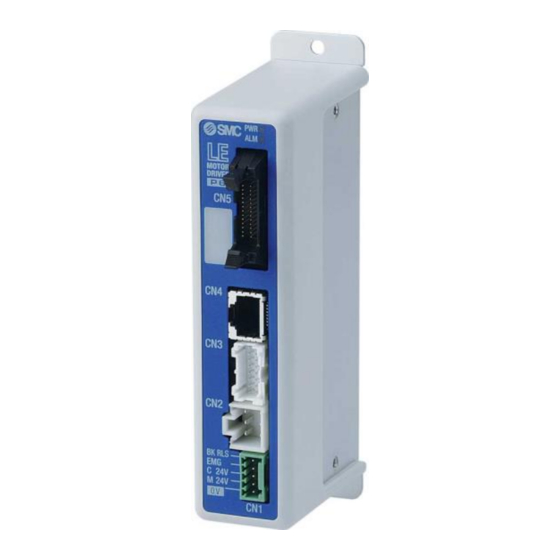
Page 17: Parts Description
3.2 Parts description The detailed descriptions of each part are as follows: A side (controller version) SV1.00 ARX8300073 Label of controller version Example) controller version “SV1.00” (10) A Side Label Name Description Power ON/No alarm: Green light Data (step data, parameter) writing /green light flashing caution Power LED (green) Do not turn off the input power supply for the controller... -
Page 18: Outside Dimension Diagram
3.3 Outside dimension diagram The outside view of this product is as shown in the diagram below: (1) Screw mount type (LECP6□□-□) (2) DIN rail mount type (LECP6□□D-□) - 17 -... -
Page 19: How To Install
3.4 How to install (1) How to install The controller can be direct mounted using screws or mounted on a DIN rail. The followings are the descriptions on how to install each type: 1) Screw mount type (LECP6□□-□) 2) DIN rail mount type (LECP6□□D-□) (Installation with the DIN rail) (Installation with two M4 screws) DIN rail is locked. -
Page 20: Installation Location
Caution The earthling should be the dedicated grounding point. It should be a functional ground with less than 100 Ω resistance. The cross section of the grounding wire should be greater than 2mm The ground point should be near this controller to make the wire length shorter. Controller Other device Controller... -
Page 21: External Wiring Diagram
4. External Wiring Diagram Examples of standard wiring are shown for each connector (CN1 to CN5) of the controller. 4.1 CN1: Power connector Controller Controller power supply 24 VDC Power cable (The 24 VDC power supply and the power cable should be obtained separately.) Please refer to “5. -
Page 22: Connection With A Pc
(2) Connection with a PC Controller setting kit Controller モニタ モニタ 120.3 120.3 動作中 動作中 現在位置 現在位置 現在速度 現在速度 mm/s mm/s アラーム アラーム 設定 設定 USB cable 位置 位置 速度 速度 テスト テスト テスト テスト 1000 1000 (A-miniB type connector) テスト... -
Page 23: Cn1: Power Supply Plug
5. CN1: Power supply plug 5.1 Power supply plug specifications Power supply plug Terminal Function Descriptions The negative common power for M24V, Common power (-) C24V, EMG and BK RLS. The positive power for the electric actuator M24V Motor power (+) motor to be supplied via the controller. -
Page 24: Wiring Of Power Supply Plug
5.3 Wiring of power supply plug Connect the power supply plug to the 24 VDC controller power supply according to instructions (1) (2) and (3) and then, insert it into the CN1 connector of the controller. (1) Wiring of the power supply Connect the positive of the 24 VDC controller power supply of the controller to the C24V, M24V and EMG terminal of the power supply connector, and connect the negative of that power supply to the 0V terminal. -
Page 25: Wiring Of The Lock Release
(3) Wiring of the lock release Install an unlocking switch for adjustment or recovery during an emergency of the electric actuator with lock. The switch (24 VDC, Contact capacity: 0.5A or more) should be obtained separately. One terminal of the lock release switch should be connected to the 24 VDC power supply and the other should be connected to the BK RLS terminal. -
Page 26: Stop Circuits
5.4 Stop circuits When the external switch to stop or the stop switch of the teaching box is enabled on this controller, the electric actuator will stop. (1) Example circuit 1 - Single controller with teaching Box When the teaching box is connected to the controller, the teaching box’s stop switch will become effective. -
Page 27: Example Circuit 2 - Multiple Controllers
(2) Example circuit 2 - multiple controllers If the system where this controller is installed has a stop circuit for whole system, or if the system has multiple controllers with individual power supply, relay contacts should be made between the 24 VDC controller power supply and the EMG terminal of the power supply plug. -
Page 28: Example Circuit 3 - Motor Power Shutdown
(3) Example circuit 3 - Motor power shutdown If there is a necessity to have circuit to shut down the motor power externally, relay contacts should be made between the 24 VDC controller power supply and the M24V and EMG terminal of the power supply plug. -
Page 29: Cn5: Parallel L/O Connector
6. CN5: Parallel l/O Connector 6.1 Parallel I/O specifications ● Input specifications ● Output specifications Item Specification Item Specification Internal circuit and photo Internal circuit and photo Output circuit Input circuit coupler Isolation coupler isolation Number of Number of outputs 13 outputs 11 inputs inputs... -
Page 30: The Parallel I/O Signal Is Detailed
6.3 The parallel I/O signal is detailed I/O cable The end to be connected to a PLC, etc. Connector for CN5 of the controller - Input terminal- Function Description COM+ The terminal for the 24V of the 24 VDC I/O signal power. COM- The terminal for the 0V of the 24 VDC I/O signal power. - Page 31 Effective condition of the Parallel I/O signal Condition SETON SVRE BUSY Signal name SETUP (Return to origin) DRIVE (Operation start instruction) (“-” = It doesn't depend in the ON/ OFF state of the each output signal) *1) During the positioning operation the SETUP input will be disabled whilst hold is in operation. Caution SETUP and DRIVE can only be accepted during the above conditions.
- Page 32 Caution continue (1) After pushing operation is finished, even if controller changes to energy saving mode, “INP” signal status maintains to ON. (Example) Step data “force” is 100% INP (ON) force Step data “Trigger LV” is 80%, The energy saving setting of the time time electric actuator is 40%...
- Page 33 The following table shows the relation of the positon number and the combination of IN0-IN5 or OUT0-OUT5. 0: OFF 1: ON 0: OFF 1: ON Step Step - 32 -...
- Page 34 0:OFF 1:ON 0:OFF 1:ON Step Step - 33 -...
-
Page 35: Parallel I/O Wiring Example
6.4 Parallel I/O Wiring Example When you connect a PLC, etc. to the CN5 parallel I/O connector, please use the I/O cable (LEC-CN5-□). The wiring should be changed depending on the type of the parallel I/O (NPN or PNP). Please wire referring to the following diagram. ●... -
Page 36: Setting Data Entry
7. Setting Data Entry In order to move the electric actuator to a specific position, it is necessary to setup the patterns of operations with the controller setting kit or the teaching box. This setup data input by the controller setting kit or teaching box will be recorded in the memory of the controller. - Page 37 Details of step data Setting name Range Description Number of the step data. 0 to 63 The setting to specify the coordinate system for the target position. Software Description Blank Disable The step data is ineffective. 3 options The target position will be defined by Movement MOD (See the right Absolute...
- Page 38 ● Effective only for the pushing operation (when the value for the “Pushing force” is from 1to 100). This defines the movement speed during the pushing operation. If this Speed Minimum value to is too high, it may cause damage to the electric actuator or work piece due to Pushing speed “Max force”...
-
Page 39: Basic Parameter
7.2 Basic parameter The “Basic parameter” is the data to define the operating conditions of the controller, conditions of the electric actuator, etc. Caution Writing of the parameter should be performed while the electric actuator is stopped. Details of basic parameter Activation: “XX”... - Page 40 This defines the position of the electric actuator after the return to origin operation. (Unit: mm) ● The ORIG offset is 0 (mm). Electric actuator Between the left examples, the The position recognized by the electric actuator positions are controller after the return to the origin operation (0mm).
-
Page 41: Return To Origin Parameter
7.3 Return to origin parameter The “Return to origin parameter” is the setting data for the return to origin operation. Details of Return to origin parameter Activation: “XX” = Become effective just after recorded into the controller, “X” = Become effective after restarting the controller, “-”... -
Page 42: Return To Origin
8. Return to origin 8.1 Return to origin After inputting the set data, it is necessary to perform a return to origin (to establish the origin point) before starting the positioning or pushing operation. (To ensure the position of origin) ●Return to origin operation The electric actuator moves in the return to origin direction (this direction is dependent on the electric actuator) from the initial position at the moment of power-on: See (1) in the diagram below. -
Page 43: Pushing Operation
8.3 Pushing operation The pushing operation is active when a Value greater than “1” is set in the Step data “pushing force ” Similar to the positioning operation, the electric actuator moves according to the settings of “Position” and “Speed” in the step data and then, when it reaches to the target position, it starts the pushing process. -
Page 44: Controller Input Signal Response Time
2) Movement of the work piece in the direction opposite to the pushing direction (The electric actuator is pushed back since the reaction force from the work piece is too large.) After completion of the pushing operation, if the reaction force from the work piece becomes larger, the electric actuator may be pushed back. -
Page 45: Operation (Example)
9. Operation (example) 9.1 Positioning operation Example) Move the electric actuator from the origin to 50mm point with 100mm/s. (Using Step No.1) Next, it shows setting example to move the electric actuator from the 50mm point to 100mm point by moving it 5 times continuously, 10mm at a time, with a speed of 50 mm/s. (Step No. 2) ●... -
Page 46: Pushing Operation
9.2 Pushing operation Example) Move the electric actuator from the origin to 100mm point with 100mm/s. (Using Step No.1) From the 100mm point, the electric actuator starts the pushing operation of 10mm/s speed and 50% or less force (the pushing distance is up to 5mm). Then, the electric actuator moves from the position where the pushing operation was completed (where INP was turned on) to the 50mm point with 50mm/s. -
Page 47: Operation Instruction
10. Operation instruction The controller is operated by selecting step data preset in the controller using the parallel I/O signals. The operating conditions are shown below. (1) Power on → Return to origin - Timing chart Power on → Return to origin - - Procedures- 1) Apply the power. -
Page 48: Positioning Operation
(2) Positioning operation - Procedures- - Timing chart Positioning operation - 1) Input step data No. (IN0 to IN5) Input the step data no. Scan the step data no. ↓ 2) DRIVE is turned ON. Power (OUT0 to OUT 5 is turned off) IN0~5 →Scan the step data number (from IN0 to IN5). -
Page 49: Hold
(4) HOLD -Procedures- - Timing chart HOLD - 1) HOLD is turned ON during the operation (When HOLD is ON). ↓ 2) BUSY is turned OFF Electric actuator (The electric actuator stops). ↓ 3) HOLD is turned OFF. ↓ Slow-down starting point 4) BUSY is turned ON (The electric actuator restarts). -
Page 50: Area Output
(7) Area output -Procedures- -Timing chart Area output - ● Operation of Step Data No.1 Example: The initial position: 50mm 1) Input step data No. (IN0 to IN5). ↓ Operation of step data No.1: Position: 200mm, Area1-Area2: 150-250mm ↓ ↓ 2) DRIVE is turned ON. -
Page 51: Alarm Detection
11. Alarm Detection The details of the alarm can be checked using the controller setting kit or the teaching box. Please refer to the manuals of the controller setting kit or the teaching box for details of the alarms. Please refer to section “12.2 Alarm details” of this manual on how to, deactivate the alarm. 11.1 Parallel output for the alarm group In case of an alarm, this controller outputs a signal that informs the type of alarm. -
Page 52: Alarm Details
11.2 Alarm details Alarm How to Alarm contents/ Countermeasure (code) deactivate <Contents> The step data is in-correct for the following conditions (Assignable value range) (1) “Area1” < “Area2” (If both “Area1 and Area2” is 0, the alarm will not be activated.) (2) “Trigger LV”... - Page 53 <Contents> For an operation for a specific step data no., the requested number of the step data is not registered. (When operation is commanded through PLC, this alarm will be generated depending on the input signal interval and the holding time of signals) Step data ALM2 RESET...
- Page 54 <Contents> A positioning operation or pushing operation is requested. Before execute the return to origin position. Drive ALM RESET (1-099) input <Countermeasure> Modify the setting so that those operations will be requested after the return to origin position is completed. <Contents>...
- Page 55 <Contents> The motor speed exceeds a specific level due to an external force, etc. <Countermeasure> RESET Over speed Make improvements such that the motor speed will not exceed SVON the maximum speed of the electric actuator. (1-144) Input Caution Please refer to the manual or the catalogue of the electric actuator for the maximum speed of the electric actuator.
- Page 56 <Contents> The output current accumulated value exceeds the specified value. RESET Over load <Countermeasure> SVON (1-148) Check whether the movement of the electric actuator is Input obstructed. Also confirm whether the electric actuator load, speed, acceleration and deceleration are within the specification range of the electric actuator.
- Page 57 <Contents> An overflow of the position error counter inside of the controller is occurred. Err overflow <Countermeasure> Power off (1-196) Make sure there are no obstructions that interfere with the electric actuator movement. Also, make sure that the load, speed, acceleration and deceleration are within the range of the electric actuators.
-
Page 58: Wiring Of Cables/Common Precautions
12. Wiring of cables/Common precautions Warning (1) Adjusting, mounting or wiring change should never be done before shutting off the power supply to the product. Electrical shock, malfunction and damag can result. (2) Never disassemble the cable. Use only specified cables. (3) Do not remove or connect the cable and connector while power is supplied. -
Page 59: Electric Actuators/Common Precautions
13. Electric actuators/Common precautions 13.1 Design and selection Warning (1) Be sure to read the Operation Manual. Handling or usage/operation other than that specified in the Operation Manual may lead to breakage and operation failure of the product. Any damage attributed to the use beyond the specifications is not guaranteed. (2) There is a possibility of dangerous sudden action by the product if sliding parts of machinery are twisted due to external forces etc. -
Page 60: Mounting
Caution (1) Operate within the limits of the maximum usable stroke. The product will be damaged if it is used with the stroke which is over the maximum stroke. Refer to the specifications of the product. (2) When the product repeatedly cycles with partial strokes, operate it at a full stroke at least once a day or every 1000 strokes. -
Page 61: Precautions For Use
13.3 Precautions for Use Warning (1) Do not touch the motor while in operation. The surface temperature of the motor can increase to approx. 90 C to 100 C due to operating conditions. Energizing alone may also cause this temperature increase. As it may cause burns, do not touch the motor when in operation. -
Page 62: Operating Environment
[Ground] Warning (1) Be sure to ground the electric actuator. (2) Grounding should be dedicated ground. Ground construction is Class D grounding. (Ground resistance 100 Ω or less) (3) Make the grounding as close as possible to the electric actuator and shorten the distance to ground. -
Page 63: Maintenance
13.5 Maintenance Warning (1) Do not disassemble or repair the product. Fire or electric shock can result. (2) Before modifying or checking the wiring, the voltage should be checked with a tester 5 minutes after the power supply is turned off. Electrical shock can result. -
Page 64: Controller And Its Peripheral Devices /Specific Product Precautions
(7) When the electric actuator is operated manually (when SVRE output signal is off), supply 24 VDC to the [BK RLS] terminal of the power supply connector. If the product is operated without releasing the lock, wearing of the lock sliding surface will be accelerated, causing reduction in the holding force and the life of the locking mechanism. -
Page 65: Installation
Check the voltage using a tester for more than 5 minute after power-off in case of installation, wiring and maintenance. There is a possibility of getting electric shock, fire and injury. (9) Do not use in an area where dust, powder dust, water or oil is in the air. It will cause failure or malfunction. -
Page 66: Power Supply
(4) Do not carry this product by holding its cables. It may cause an injury or damage to the product. (5) Do not connect power cable or high-voltage cable in the same wiring route as the unit. The wires to the controller or its peripheral devices can be interrupted with noise or induced surge voltage from power lines or high-voltage lines and malfunction could be caused. -
Page 67: Troubleshooting
15. Troubleshooting In case of any troubles, please consult the following table. Consider replacing controller, if not of the causes on this table are applicable. It is possible that this product is damaged due to the operating conditions (applications), please contact SMC to discuss appropriate measures. - Page 68 Trouble Possible Trouble How to diagnose the trouble Solutions cause The power supply, voltage or current Check if the LED (green) of the should be modified to an appropriate one. Power fault →4. External Wiring Diagram controller is lit. →5. CN1: Power supply plug Check if the wiring is connected correctly or if there is broken wire or short-circuit by referring to this...
- Page 69 If there is no sound of lock release from Check if you can hear the sound Lock release the electric actuator with lock, the lock of lock release when the manual error may be broken. If the trouble lock switch is turned on and off. continues, please contact SMC.
- Page 70 If the controller version is below SV1.00 Check during pushing operation The pushing force is reduced when the the INP output signal is turning energy saving mode is turned on. If the The pushing pushing force is reduced to a value less (On completion of pushing the than the value in step data “trigger LV”...
- Page 71 Check if the wiring is connected correctly or if there is broken wire or short-circuit by referring to this Operation Manual. Correct the wiring and check that the Is the wiring connected input/output of each signal is correct. Wiring fault correctly? Separate the power supply for the CN1controller and the CN5 I/O signal...
- Page 72 Revision history No.LEC-OM00601 Sep/2008 1st printing No.LEC-OM00602 Apr/2009 Revision No.LEC-OM00603 Apr/2010 Revision No.LEC-OM00604 Jul/2011 Revision Addition/Standard cable Addition/Operation trouble Addition/Timing chart No.LEC-OM00605 Apr/2012 Revision Addition to notes about UL recognition No.LEC-OM00606 Jan/2014 Revision Addition/Troubleshooting No.LEC-OM00607 Jan/2015 Revision Addition/EMG signal Instructions No.LEC-OM00608 May/2015 Revision Addition/ Step no.
Need help?
Do you have a question about the LECP6 Series and is the answer not in the manual?
Questions and answers