
Subscribe to Our Youtube Channel
Related Manuals for SMC Networks LECP1 Series


Summary of Contents for SMC Networks LECP1 Series
- Page 1 Doc. no.LEC-OM03901 PRODUCT NAME Programless controller Step motor (servo 24 VDC ) MODEL/ Series LECP1 Series...
-
Page 2: Table Of Contents
Contents 2. Outlines of Product ..........................5 2.1 Features ............................5 2.2 How to Order ..........................6 2.3 Structure of the product ........................ 7 2.4 Procedure (How to start the actuator) ..................8 (1) Checking the contents of the package ..................8 (2) Mounting the Controller ...................... - Page 3 8.5 Servo ON ..........................43 8.6 Response time for the controller input signal ................43 9. Operation (Example) ........................44 9.1 Positioning / Return to origin position ..................44 9.2 Pushing operation........................45 9.3 Stoppage during operation....................... 46 9.4 Generation and deactivation of alarm..................47 10.
- Page 4 LECP1 Series / Controller Safety Instructions These safety instructions are intended to prevent hazardous situations and/or equipment damage. These instructions indicate the level of potential hazard with the labels of “Caution,” “Warning” or “Danger.” They are all important notes for safety and must be followed in addition to International Standards (ISO/IEC), Japan Industrial Standards (JIS)*1) and other safety regulations*2).
- Page 5 LECP1 Series / Controller Safety Instructions Caution The product is provided for use in manufacturing industries. The product herein described is basically provided for peaceful use in manufacturing industries. If considering using the product in other industries, consult SMC beforehand and exchange specifications or a contract if necessary.
-
Page 6: Outlines Of Product
2. Outlines of Product 2.1 Features Features of the controller. Actuator control Servo control enables the positioning and the operation with a specified thrust of the actuator. Operation and settings are available with the controller. Settings can be altered and operation can be fun from the controller. Adjustments of the position, speed, acceleration and test runs are available without the teaching box, PC, and PLC. -
Page 7: How To Order
2.2 How to Order How to order is shown below. Controller L E C P 1 N □ - □ Controller Actuator Model Applicable motor (Enter from the actuator model "LE" to ”stroke”) Step motor (servo DC24V) Ex: LEHZ10LK2-4AF-R11N1 Enter "LEHZ10LK2-4" Step data 14 points (Programless) Parallel input / output type... -
Page 8: Structure Of The Product
2.3 Structure of the product Structure of the controller. ● I/O cable Part no.: LEC-CK4-* ● Electric actuator Input/output signal power supply ● Actuator cable [Robot cable] To CN4 Part no.: LE-CP-* [Standard cable] Part no. :LE-CP-*S To CN3 To CN2 ●... -
Page 9: Procedure (How To Start The Actuator)
2.4 Procedure (How to start the actuator) Install, wire, set and operate the controller referring to the procedure below when the product is used for the first time. (1) Checking the contents of the package After unpacking everything, check the description on the label to identify the controller and the number of accessories. -
Page 10: Alarm Check
(4) Power supply ON Alarm check Supply power 24V DC. Description LED turns on Condition Green LED is on Servo is on Green LED is flashing Servo is turned off ALARM Alarm is generated Controller If the conditions are normal, the LED[PWR] at the front of the controller switches from a flashing to a solid light. -
Page 11: Specifications
3. Specifications 3.1 Basic specifications Basic specifications of the product. Item Specifications Controlled motor Step motor(servo 24VDC) Power supply voltage: 24VDC±10% Power supply Max. current consumption: Rated 3.2A (Peak 5A)(*2) specification (*1) [Includes the motor power supply, control power supply, stop, unlocking] Parallel input Input 6 points (Photo coupler insulation) -
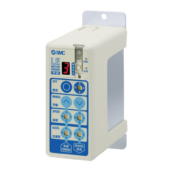
Page 12: Details Of The Controller
3.2 Details of the controller ○ ○ ○ Details Display Description Power Power supply ON/No alarm :Green turns on ○ ○ supply LED Power supply ON/servo OFF :Green flashes ○ Power supply ON/With alarm :Red turns on ○ ○ Alarm LED Power supply ON/Parameter setting:... -
Page 13: Outer Dimensions
Caution Use a flat blade watchmaker's screwdriver of the size shown below when changing position ○ ○ ○ switch h and the set value of the speed/acceleration switch k to <Size> End width L :2.0 to 2.4 [mm] End thickness W :0.5 to 0.6 [mm] Magnified view of the end of the flat blade screwdriver 3.3 Outer dimensions The appearance of the product is shown below. -
Page 14: Mounting
3.4 Mounting (1) Mounting Details of the controller. Mounting screw (LECP1□□-□) (Mounting with two M4 screws) Grounding cable Mounting direction Mounting direction (2) Grounding Tighten the bolt with the nut when mounting the ground cable as shown below. M4 screw Cable with crimping terminal Serrated washer Controller... -
Page 15: Location For Mounting
Caution (1) Grounding shall be done by dedicated cable. Grounding with the ground resistance of 100Ω or less. (2) The cross sectional area of the grounding cable shall be 2mm or more. Grounding location shall be in the vicinity of the controller. Keep the grounding cable short. Other Other Controller... -
Page 16: External Connection
4. External connection 4. 1 CN1: Power supply connector The example of standard wiring of the controller is shown per connector (CN1 to 4). Controller Controller input power supply 24VDC Power supply cable (Controller input power supply of 24V DC is prepared by customer. -
Page 17: Cn1: Power Supply Cable
5. CN1: Power supply cable 5. 1 Power supply cable specification Included power supply cable specification is shown below. Power supply cable (LEC-CK1-1) 6.0) (60) (35) (10.5) (13.3) Item Specifications Connector Manufacturer: J.S.T. Mfg. Co.,Ltd. Product number :VHR-4N Cross sectional AWG20 area of the cable LEC-CK1-1:1.5m only... -
Page 18: Power Supply Cable Specification
5. 2 Power supply cable specification Referring to (1) to (4), connect the power supply cable included in accessories to the controller input power supply 24VDC and insert it to the controller CN1 power supply connector. (1) Wiring of power supply Connect the plus (+) of the controller input power supply 24VDC to C24V terminal of the power supply cable, and connect the minus (-) to 0V terminal. -
Page 19: Stop The Power Supply For The Motor
(4) Stop the power supply for the motor If it is necessary to shut off the power supply for the motor from outside, connect the relay between the input power supply for the controller 24VDC and the power supply plug for the controller M24V. 【Example of the circuit】... -
Page 20: Cn4: Parallel I/O Cable
6. CN4: Parallel I/O cable 6.1 Paralles input / output ■Output specifications ■Input specifications Item Specifications Item Specifications Internal circuit Internal circuit and the Input circuit Output circuit photo coupler insulation photo coupler insulation No. of output 6 opints No. of inputs 6 points Voltage DC24V±10%... -
Page 21: Parallel Input / Output Signal
6.3 Parallel input / output signal I/O cable(LEC-CK4-□) ( 7.9) (10) (11) (30) (60) PLC side Controller side Item Specifications Manufacturer: J.S.T. Mfg. Co.,Ltd.Manufacturer: J.S.T. Mfg. Co.,Ltd. Connector Product number :PADP-14V-1-S Cross sectional AWG26 area of the cable The suffix of the part number (1,3,5) specifies the length. LEC-CK4-1: 1.5m Length (L)... - Page 22 The change of I/O output signal under the condition of controller at auto mode. Output signal Condition of the controller OUT0 OUT1 OUT2 OUT3 BUSY ALARM Supply of power After supplying power and at the stop before returning to origin position During the returning to origin position, positioning, and pushing...
-
Page 23: Parallel I/O Connector Wiring (Example)
6.4 Parallel I/O connector wiring (Example) Use an I/O cable (LEC-CK4-□) when connecting to PLC and CN4 parallel I/O connectors. Wiring depends on the parallel input/output of the controller (NPN, PNP type). Please wire the product referring to the wiring diagram, ■NPN TYPE ■PNP TYPE I/O signal power... -
Page 24: Setting Method
7. Setting method It is necessary to set the stop position and operation method using the controller in order to move the actuator to the specified position. Set data is stored in the memory in the controller ○ Up to 14 points can be set. Set "1" to "14" with the position switch h . -
Page 25: Setting Procedure
7.1 Setting procedure Follow the procedure below for setting. (1)Supply of power ○ ○ ○ (2)Changes to Manual mode ○ (3)Return to origin position ○ ○ Repeat (4)Setting of position same procedure (5)Setting of operation method for all points would like to set. - Page 26 (4), (5) Setting of position and operation method At the manual mode after returning to origin, position can be set by (A) Jog / inching or (B) Direct teaching. Example) Setting of position number 3 7-segment ○ (A) Setting by Jog / inching ○...
- Page 27 ○ [3] Perform Jog / inching using Forward button ○ Reverse button to move to desired position. * Jog starts by keeping pressing Forward button Forward Reverse ○ ○ ○ button or Reverse button j .Refer to 8.4 Jog / ○...
- Page 28 7-segment ○ [6] Press set button for 2 sec. to set the ○ operation method. Once this operation ○ completed, 7-segment LED display flashes quickly. The position and the operation method ○ button are stored in the controller. Positioning by jog / inching completed. Do the same for other position numbers you desire to set.
- Page 29 ○ [2] Set the position switch h to the position you 7-segment desire ("3" in this case). The value of position ○ ○ switch flashes quickly on 7-segment LED ○ Position ○ switch * Do not set "0" and "F(15)", They are not position numbers.
- Page 30 7-segment ○ [5] 7-segment LED f , Set the operation method of ○ f ○ this position by pressing the Forward button ○ Reverse button while monitoring ○ 7-segment LED * Actual force of pushing force depends on the Reverse Forward actuator.
- Page 31 (6) Test run Operate by the controller buttons and the switches to check the operation method and the position. ○ ○ ○ Operation method is as follows. ○ 1) Set the position switch h to the position number you desire. 2) Confirm that the position number flashes on the ○...
-
Page 32: Setting Parameters
7.2 Setting parameters In manual mode, it is possible to set parameters when necessary. Example. Change the jog speed level from "1" (default condition) to "3" ○ (1)Switch the controller mode switch e to manual mode (M). Mode (Example. "4" (Default value of position switch) ○... - Page 33 7-segment ○ (4) If you set the position switch to the ○ parameter No. that you desire ("2" in this case), ○ the value of the position switch h is displayed with a dot in the corner or the 7-segment LED Position ○...
- Page 34 ○ (7) Press forward button and reverse button Mode ○ to adjust the parameter to the desired value ○ switch ○ ("3" in this example). Press the set button for 2 sec. to set after the adjustment. ○ button Forward Reverse * When this operation is completed, the 7-segment ○...
-
Page 35: Controller Modes
7.3 Controller modes Controller modes are divided into two types, auto mode and manual mode. There are several status types in one mode. The figure below shows how the status changes. Supply power Auto mode Manual mode Switching of mode SW Jog / Waiting Waiting... -
Page 36: (A) Before Returning To Origin Position
(A) Before returning to origin position The transition of the status before returning to origin is shown below. After turning on the power supply, ○ the controller status is in waiting mode which is set by mode switch e . The operation of jog / inching at manual mode is available before retuning to origin. -
Page 37: (B) Auto Mode After Return To Origin Position
(B) Auto mode after return to origin position The status of the auto mode after return to origin position is shown below. At auto mode, only the operation command such as I/O from PLC is accepted. Basically, position, operation method, speed and acceleration cannot be adjusted in auto mode. -
Page 38: (C) Manual Mode After Retuning To Origin Position
(C) Manual mode after retuning to origin position The status of the manual mode after return to origin position is shown below. In manual mode, return to origin is controlled by the operation of the controller buttons and switches. The speed and acceleration can be adjusted any time. -
Page 39: Test Function
7.4 Test function The table below shows the difference between normal operation and test function in manual mode. To ○ ○ start the test function, set the position switch h to "0" while the power LED a is on (= servo ON) ○... -
Page 40: Operations
8. Operations 8.1 Returning to origin position When the power is supplied, it is necessary to return to origin for positioning or pushing of the actuator. (To ensure the position of origin) ■Input of the return to origin position There are 2 ways for returning to origin per mode, ○... -
Page 41: Positioning
8.2 Positioning The actuator travels to the target position at Ex. Positioning speed and acceleration which are set per Speed Positioning range operating direction. Operation complete signal is output when the actuator reaches the Set speed positioning range of the target position. Position Load Actuator... -
Page 42: Unsuccessful Pushing Operation (Idling)
(2) Unsuccessful pushing operation (Idling) If pushing is not completed when the actautor moves from the start position until the actuator's end, it is pushed back at the actuator end and the completion signal is generated. Speed Set speed Pushing speed Position Pushing thrust Load... -
Page 43: Jog / Inching Operation
8.4 Jog / inching operation ○ ○ Jog / inching is available by pressing forward button or reverse button at manual mode. Jog / inching can be performed before retuning to origin. Operation method ○ ○ Inching starts and stops by pressing forward button or reverse button j . -
Page 44: Servo On
8.5 Servo ON ○ Servo ON signal is not assigned to the parallel I/O of this controller. The power supply LED changes flashing to lighting after specific period of time after power supply and the servo turns on. The table below shows conditions for servo OFF Conditions for servo OFF Indication of servo OFF ○... -
Page 45: Operation (Example)
9. Operation (Example) 9.1 Positioning / Return to origin position Ex). If the operation pattern is Return to origin --> Position 1 --> Position 2 --> Position 1, Forward: Speed 5, acceleration 3 (Switch value) Reverse: Speed 9, acceleration 7 (Switch value) Origin Actuator end Initial position... -
Page 46: Pushing Operation
9.2 Pushing operation Ex.) If the operation pattern is Position 3 --> Position 4 --> Position 3 --> Position 5. Forward: Speed 5, acceleration 3 (Switch value) Actuator end Reverse: Speed 9, acceleration 7 (Switch value Position NO.3 Position NO.4 Position at which pushing to the reverse direction from... -
Page 47: Stoppage During Operation
9.3 Stoppage during operation Ex.) Position No.6 -> Stop by inputting the RESET signal while the actuator is traveling to position No.7 -> Position No.8 -> Stop by inputting the STOP signal while the actuator is traveling to position No.7 -> Position No.9 Actuator end Forward: Speed 5, acceleration 3 (Switch value) Position NO.6... -
Page 48: Generation And Deactivation Of Alarm
9.4 Generation and deactivation of alarm Ex.) Position No.10→Alarm generated during the travel to Position No. 11→Troubleshoot, deactivate the alarm→Travels to position No.11→Travels to Position No.10 Forward: Speed 5, acceleration 3 (Switch value) Reverse: Speed 9, acceleration 7 (Switch value) Actuator end Position No.10 Position No.11... -
Page 49: Initial Setting Value Per Actuator
10. Initial setting value per actuator 10.1 Initial setting value of LEF series Initial setting value of LEF series Refer to the table below for the initial setting of the Return to origin, jog and inching. LEFB LEFS 16,25,32 common Direction Side of the motor Return to... - Page 50 Refer to the table below for the speed and the acceleration table of the LEFS series. LEFS16A LEFS16B LEFS25A LEFS25B speed acceleration speed acceleration speed acceleration speed acceleration [mm/s] [mm/s [mm/s] [mm/s [mm/s] [mm/s [mm/s] [mm/s 1000 1000 1000 1000 1200 1200 1200...
-
Page 51: Initial Setting Value Of Leh Series
10.2 Initial setting value of LEH series Initial setting value of LEF series Refer to the table below for the initial setting of Return to origin, jog and inching. Common with LEHF series Common with LEH(S, Z) series Direction Side to be closed (Clamped side) Return to speed [mm/s] origin... - Page 52 Refer to the table below for the speed / acceleration of LEHF series. LEHF10 LEHF20 LEHF32 LEHF40 acceler acceler acceler accele speed speed speed speed ation ation ation ration [mm/s] [mm/s] [mm/s] [mm/s] [mm/s [mm/s [mm/s [mm/s 1000 1000 1000 1000 1200 1200...
- Page 53 Refer to the table below for the speed / acceleration of LEHZ series. LEHZ10 LEHZ16 LEHZ20 LEHZ25 speed acceleration speed acceleration speed acceleration speed acceleration [mm/s] [mm/s [mm/s] [mm/s [mm/s] [mm/s [mm/s] [mm/s 1000 1000 1000 1000 1200 1200 1200 1200 1400 1400...
-
Page 54: Initial Setting Value Of Les Series
10.3 Initial setting value of LES series Initial setting value of LES series Refer to the table below for initial setting of Return to origin, jog and inching. Common for all series of LES Direction Side to be retracted Return to origin speed [mm/s] acceleration [mm/s speed [mm/s]... -
Page 55: Initial Setting Value Of Ley Series
10.4 Initial setting value of LEY series Initial setting value of LEY series. Refer to the table below for initial setting of Return to origin, jog and inching. Common for all series of LEY Direction Side to be retracted Return to home speed [mm/s] origin acceleration [mm/s... - Page 56 LEY25A LEY25B LEY25C speed acceleration speed acceleration speed acceleration [mm/s] [mm/s [mm/s] [mm/s [mm/s] [mm/s 1000 1000 1000 1200 1200 1200 1400 1400 1400 1600 1600 1600 1800 1800 1800 2000 2000 2000 2500 2500 2500 3000 3000 3000 LEY32A LEY32B LEY32C speed...
-
Page 57: Initial Setting Value Of Ler Series
10.5 Initial setting value of LER series Initial setting value of LER series Refer to the table below for initial setting of Return to origin, jog and inching. LER□□□K series LER□□□J series Direction Counterclockwise(CCW) Counterclockwise(CCW) Return to origin speed [°/s] acceleration [°/s 1000 1000... -
Page 58: Options
11. Options 11.1 Actuator cable [5m or less] ① ② L E - C P - □ □ Signal TerminalNo. Cable color TerminalNo. Brown (L) Cable length Orange 1.5m Yellow COM-A/COM Green COM-B/ - Blue ③ Shield Cable color TerminalNo. Brown Actuator cable type... -
Page 59: Actuator Cable (For Sensor / Lock) [5M Or Less]
11.3 Actuator cable (for sensor / lock) [5m or less] ① L E - C P - □ □ - B ② Signal TerminalNo. Cable color TerminalNo. Brown Cable length (L) Orange 1.5m Yellow COM-A/COM Green COM-B/ - Blue ③ Shield Cable color TerminalNo. -
Page 60: Alarm Detection
12. Alarm detection Details of the alarm can be checked by the controller LED indication and parallel I/O terminal. When an alarm is generated, deactivate the alarm by troubleshooting, referring to 12.2 Alarm Content・Countermeasure (P.60). ○ Alarms are divided into two types. One type can be cleared by pressing the set button g or inputting the RESET I/O signal. -
Page 61: Alarm Content・Countermeasure
12.2 Alarm Content・Countermeasure condition of How to clear controller Condition / Countermeasure when an alarm alarm is generated <Condition> Problem occurred with the controller data or parameters. Input condition RESET <Countermeasure> If the problem is not solved by supplying power again, contact SMC. <Condition>... - Page 62 condition of How to clear controller Condition / Countermeasure when an alarm alarm is generated <Condition> The power supply voltage for motor which is detected in the controller is out of the specified range. The regenerative electricity of the motor is large while using the brake .
- Page 63 condition of How to clear controller Condition / Countermeasure when an alarm alarm is generated <Condition> Power Positioning of the polarity is not finished properly. When the power is supply supplied, the actuator slightly moves to detect the polarity of the motor. When the This alarm is generated when the actuator cannot be moved.
-
Page 64: Wiring Of Cables/Common Precautions
13. Wiring of cables/Common precautions Warning Adjusting, mounting or wiring change should never be done before shutting off the power supply to the product. Electrical shock, malfunction and damaged can result. Never disassemble the cable. Use only specified cables. Never connect or disconnect the cable or connector with power on. Caution Wire the connector securely. -
Page 65: Electric Actuators/Common Precautions
14. Electric actuators/Common precautions 14.1 Design and selection Warning 1. Be sure to read the Operation Manual. Handling or usage/operation other than that specified in the Operation Manual may lead to breakage and operation failure of the product. Any damage attributed to the use beyond the specifications is not guaranteed. There is a possibility of dangerous sudden action by the product if sliding parts of machinery are twisted due to external forces, etc. -
Page 66: Mounting
Refer to a common auto switch /matter (Best Pneumatics No. 2) when an auto switch is built in and used. Return to origin cannot return while operating. It cannot be done during positioning operation, pushing operation and pushing. 14.2 Mounting Warning Install and operate the product only after reading the Operation Manual carefully and understanding its contents. - Page 67 Immediately stop operation if abnormal operation noise or vibration occurs. If abnormal operation noise or vibration occurs, the product may have been mounted incorrectly. Unless operation of the product is stopped for inspection, the product can be seriously damaged. Never touch the rotating part of the motor or moving part of the actuator while in operation. When installing, adjusting, inspecting or performing maintenance on the product, controller and related equipment, be sure to shut off the power supply to each of them.
-
Page 68: Operating Environment
14.4 Operating environment Warning Avoid use in the following environments. a. Locations where a large amount of dusts and cutting chips are airborne. b. Locations where the ambient temperature is outside the range of the temperature specification (refer to specifications). c. -
Page 69: Precautions For Actuator With Lock
Caution Maintenance should be performed according to the procedure indicated in the Operating Manual. Incorrect handling can cause injury, damage or malfunction of equipment and machinery. Removal of product. When equipment is serviced, first confirm that measures are in place to prevent dropping of work pieces and run-away of equipment, etc, and then cut the power supply to the system. -
Page 70: Controller And Its Peripheral Devices / Specific Product Precautions
15. Controller and its peripheral devices / Specific product precautions 15.1 Design and selection Warning 1. Be sure to apply the specified voltage. Otherwise, a malfunction and breakage of the controller may be caused. If the applied voltage is lower than the specified, it is possible that the load cannot be moved due to an internal voltage drop. -
Page 71: Installation
applied to the product. It will cause failure of the controller or its peripheral devices. 13. Do not use the product in an environment subject to a temperature cycle. It will cause failure of the controller or its peripheral devices. 14. -
Page 72: Power Supply
15.5 Power supply Caution 1. Use a power supply that has low noise between lines and between power and ground. In cases where noise is high, an isolation transformer should be used. 2. The power supplys should be separated between the controller power and the I/O signal power and both of them do not use the power supply of “rush-current restraining type”... -
Page 73: Troubleshooting
16. Troubleshooting Refer to the table below for troubleshooting. When none of the causes in the troubleshooting can be confirmed and normal operation is recovered by the replacement of a part, it is presumed that failure is in the product. Problems with the product may be due to the operating environment (application). - Page 74 Investigation method and the Failure Possible Countermeasure location of possible causes Problem causes Controller alarm is generated? Check the type of the alarm Refer to the operation manual of the Alarm controller. referring to the operation manual generated -->12. Alarm detection (P.59) of the controller for troubleshooting.
-
Page 75: Position / Speed Troubles
16.2 Position / Speed troubles Investigation method and the Failure Possible Countermeasure location of possible causes Problem causes In case of return to origin with pushing operation, does the Displaced actuator travel to the origin? Check if foreign matter is caught in the from the Perform return to origin several product by operating the actuator. - Page 76 Revision history No. LEC-OM03901 Jun / 2011 1st printing 4-14-1, Sotokanda, Chiyoda-ku, Tokyo 101-0021 JAPAN Tel: + 81 3 5207 8249 Fax: +81 3 5298 5362 http://www.smcworld.com Note: Specifications are subject to change without prior notice and any obligation on the part of the manufacturer. ©...
Need help?
Do you have a question about the LECP1 Series and is the answer not in the manual?
Questions and answers