Table of Contents
Advertisement
Quick Links
No. DOC1068298
NN68575001
PRODUCT NAME
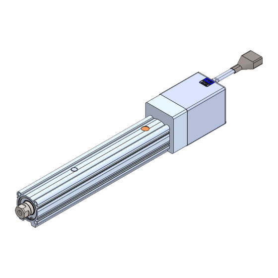
Electric Actuator/Rod Type
compatible with manifold controller
《
》
(
)
Battery less absolute encoder type
step motor DC24V
MODEL / Series / Product Number
LE2Y series
Applicable models : LE2Y□H
* The descriptions in this operation manual are based on the selection of "Controller/JXD1-M*".
* For details of the controller, please refer to the operation manual of the controller as well.
Advertisement
Table of Contents

Related Manuals for SMC Networks LE2Y Series


Summary of Contents for SMC Networks LE2Y Series
- Page 1 Battery less absolute encoder type step motor DC24V MODEL / Series / Product Number LE2Y series Applicable models : LE2Y□H * The descriptions in this operation manual are based on the selection of "Controller/JXD1-M*". * For details of the controller, please refer to the operation manual of the controller as well.
-
Page 2: Table Of Contents
Contents Safety Instructions ..............2 Precautions for product specific ..............4 1 Outline of Product............24 1.1 System Construction Example ............ 24 1.2 Features ....................24 1.3 How to Order ..................25 1.4 Specifications ..................26 1.5 Construction ..................28 1.6... -
Page 3: Safety Instructions
Electric Actuator/Rod Type compatible with manifold controller Safety Instructions These safety instructions are intended to prevent hazardous situations and/or equipment damage. These instructions indicate the level of potential hazard with the labels of “Caution,” “Warning” or “Danger.” They are all important notes for safety and must be followed in addition to International Standards (ISO/IEC) *1), and other safety regulations. - Page 4 Electric Actuator/Rod Type compatible with manifold controller Safety Precautions Caution We develop, design, and manufacture our products to be used for automatic control equipment, and provide them for peaceful use in manufacturing industries. Use in non-manufacturing business is not covered. Products we manufacture and sell cannot be used for the purpose of transactions or certification specified in the Measurement Act.
-
Page 5: Precautions For Product Specific
Precautions for product specific Precautions for wiring and cable Warning ① Installation, adjustment, inspection, or wiring changes should be conducted with the power supply to this product turned OFF. Electrical shock, malfunction, or damage can result. ② Never disassemble the cable. ③... - Page 6 ⑨ When the actuator cable is to be bent repeatedly, do not route it in a movable wiring duct smaller than the minimum specified radius (For cable lengths of 10 m or less: bend radius = 56 mm minimum; For cable lengths of 15 m or more: bend radius = 77 mm minimum).
- Page 7 ③ A protective cover is recommended to minimize the risk of personal injury. If a driven object and moving parts of the product are in proximity, personal injury may occur. Design the system to avoid contact with the human body. ④...
- Page 8 ② When the product repeatedly cycles with partial strokes, operate it at a full stroke at least once every few 10 strokes. Otherwise, lubrication can be lost. ③ Do not use the product in applications where exces- sive external force or impact force is applied to it.
- Page 9 ⑨ When mounting the actuator or attaching the work piece, do not apply strong impact or large moment. If an external force above the allowable moment is applied, it may cause looseness in the guide unit, an increase in sliding resistance or other problems. ⑩...
- Page 10 ⑥ The inside of the electric actuator and its connector should not be touched. It may cause an electric shock or damage to the controller. ⑦ Do not perform the operation or setting of the product with wet hands. Doing so may cause an electric shock. ⑧...
- Page 11 ⑳ In the case of an actuator that has a servo motor (24 VDC), the motor phase detection step is conducted by inputting the servo ON signal just after the controller power is turned on. The motor phase detection step moves the table/rod by a distance of one screw-lead maximum.
- Page 12 ⑤ Avoid common grounding points shared with other devices. ■ Power supply Caution ① Use a power supply that has low noise between lines and between the power and ground. In cases where noise is high, an isolation transformer should be used. ②...
- Page 13 ④ Shade the sunlight in the place where the product is applied with direct sunshine. ⑤ Shield the product if there is a heat source nearby. When there is a heat source surrounding the product, the radiated heat from the heat source can increase the temperature of the product beyond the operating temperature range.
- Page 14 Caution ① Maintenance should be performed according to the procedure indicated in the Operation Manual. Incorrect handling can cause an injury, damage or malfunction of equipment and machinery. ② Removal of product When equipment is serviced, first confirm that measures are in place to prevent dropping of work pieces and run-away of equipment, etc., and then cut the power supply to the system.
- Page 15 ⑦ If the mover of electric actuator with lock is intentionally moved by external force (e.g. spring, human power, etc.), supply 24 V DC of the lock release power supply to the LKRLS1 and LKRLS2 terminals of the power supply blocking plug after the controller input power supply primary side is shut off.
- Page 16 ③ Keep the specifications driving speed range for pushing operation. This may lead to damage and malfunction. ④ Check the specification for the minimum speed of the actuator. Operation outside the specifications may cause malfunctions such as knocking. ⑤ The actual speed of the product can be changed by the load. When selecting a product, check the catalog for instructions regarding selection and specifications.
- Page 17 To screw a bracket or a nut onto the threaded portion at the tip of the piston rod, make sure to retract the piston rod entirely, and place a wrench over the flat portion of the rod that protrudes. Tighten it by giving consideration to prevent the tightening torque from being applied to the non-rotating guide.
- Page 18 <How to install the LE2Y Series> Work fixed/ Rod end female thread Max. screw Tip socket Tightening Bolt Model depth opposite used [N・m] [mm] side[mm] LE2Y16 M5x0.8 3±10% 12.5±10% LE2Y25 M8x1.25 Socket LE2Y32 M8x1.25 12.5±10% Work fixed/ Rod end male thread Max.
- Page 19 ■ Maintenance Caution ① Cut the power supply during maintenance and replacement of the product. 【 Maintenance frequency 】 Preform maintenance according to the table below. Please contact SMC if there are any problems Appearance Frequency Belt check check 〇 Inspect daily before operating Inspection every six months / 〇...
- Page 20 【Grease application】 If grease lubrication performance is reduced due to operating environment or operating conditions, please re-apply grease. 1. Grease application to the piston rod Fully extend the piston rod by performing a JOG operation and apply grease to the base of the piston rod.
- Page 21 【 Items for belt check 】 Check the belt regularly as shown in “maintenance frequency”. Stop operation immediately and contact SMC when the belt appears to be like the photographs shown below. a. Tooth shape canvas is worn out Canvas fiber becomes fuzzy. Rubber is removed and the fiber becomes white in color. Lines of fibers become unclear.
- Page 22 ■ Replacement of belt ① After screws are removed, the "Pulley plate" and “Motor cover” are removed. Screws Screws ② The motor fixing screws are loosened (To extent in which the slide can be done), the "Bearing support" is removed, and the "Belt" is removed. Screws ③...
- Page 23 Air cylinder installation with an auto switch is forbidden in the shaded area. (Example 2) When installing electric actuator LEY(G) or LEF、EQF、EQY、LE2F、LE2Y series with an auto switch side by side, leave a gap of 40 mm or more with respect to the position where the magnet passes.
- Page 24 (Example 3) Multiple actuators can be placed close to each other as shown in the figure below, as long as magnets are not close around the motor section. Caution ① Supply power when the actuator is stationary. The electric actuator acquires the absolute position data from the absolute encoder when power is applied.
-
Page 25: 1 Outline Of Product
1 Outline of Product 1.1 System Construction Example See below for an example of a system configuration using the controller. Operation Manual "Manifold Controller for Electric Actuators / JXD1-M*". 2.2 Product Configuration 1.2 Features The main functions of the electric actuator are shown below. ●... -
Page 26: How To Order
1.3 How to Order How to order is shown below. L E 2 Y 25 :Size Motor mounting position Motor cable exit direction :Battery-less absolute(Step motor 24VDC) Motor type Lead 10~500 :Stroke ※Refer to the applicable stroke table for details. :Without lock Motor option :With lock... -
Page 27: Specifications
1.4 Specifications Battery-less absolute encoder type (Step motor 24 VDC) Model LE2Y16 LE2Y25 LE2Y32 Stroke [mm] 30 to 300 30 to 400 30 to 500 Horizontal Work load [kg] Note.1) Vertical Pushing force[N] Note2),3),4) 23 to 41 44 to 80 86 to 154 41 to 81 67 to 135 132 to 265 255 to 511 60 to 140... - Page 28 Weight Motor mounting position: In-line Series LE2Y16 Stroke[mm] Weight[kg] 0.76 0.80 0.91 1.07 1.18 1.30 1.41 Additional weight 0.19 with lock[kg] Series LE2Y25 Stroke[mm] Weight[kg] 1.43 1.50 1.68 1.97 2.14 2.32 2.50 2.68 2.86 Additional weight 0.34 with lock[kg] Series LE2Y32 Stroke[mm] Weight[kg]...
-
Page 29: Construction
1.5 Construction When the rod end male thread is selected Component Parts Description Material Note Description Material Note Body Aluminum alloy Anodized Pulley/Hub Aluminum alloy Ball screw assembly Pulley /Hub Aluminum alloy Piston Aluminum alloy Retaining ring Piston rod Stainless steel Hard chrome plating Retaining ring Steel for spring... -
Page 30: Accessories
1.6 Accessories Rod end thread Accessories Rod end thread Part name Rod end male Male thread Mounting bracket Motor mounting Accessories position Mounting Part name Parallel In-line Foot bracket ● Foot type Mounting bolt Flange ● ● Rod side Flange type Mounting bolt Flange Head side Flange... -
Page 31: 2 Installation And Initial Setting
2 Installation and Initial Setting 2.1 Flow procedure from installation to initial setting Be sure to check the procedure below before use. Procedure 1 Preparation →Item2.2 ① Checking the contents of the package *: Please confirm that the actuator, accessories, and optional items are present. →Item2.3... -
Page 32: Check The Contents Of The Package
2.2 Check the contents of the package After unpacking everything, check the description on the label to identify the electric actuator and the number of accessories. If any parts are missing or damaged, please contact your distributor. Product Name and Number Quantity Electric actuator Actuator... -
Page 33: Installation Of Electric Actuators
2.4 Installation of electric actuators Install the electric actuator at the installation location using the following method. (1) Mounting Refer to Electric actuators / Common precautions in Precautions for product specific for information on screws and tightening torques to be used for mounting workpieces and tools and for mounting the actuator. -
Page 34: Wiring And Connection
2.5 Wiring and Connection Prepare the electric actuator LE2Y series and Manifold controller. Connect the Driver unit of Manifold controller and the electric actuator with the actuator cable. 7. Wiring in the instruction manual For wiring details of the manifold controller, please refer to "Manifold controller for electric actuator/JXD1-M*". -
Page 35: 4 Operation Guide
4 Operation Guide For the mechanism of each operation, refer to the following pages of the operation manual "Manifold Controller for Electric Actuators / JXD1-M*". 11.1 Return to Origin 11.2 Positioning Operation 11.3 Pushing Operation 11.4 Response Time to Controller Input Signals 11.5 Interruption method during operation 5... -
Page 36: 7 Setting
7 Setting 7.1 Parameter Setting of operation condition and other conditions of the electric actuator. Caution Write the parameter when the electric actuator is in the stopped condition. Details of parameters The parameters can be set using the setup software ACT-Connected. Write column : ◎= Effective immediately after writing to the electric actuator, 〇= Effective when the power supply is turned on again. - Page 37 Default value Setting Lead Description Input range Load LE2Y16 LE2Y25 LE2Y32 Indicates the range where INP turns ON at the position 0.01 to ◎ Initial position width after homing.(Unit:0.01mm) Product stroke Sets the level of followability of acceleration/deceleration. Acceleration and Followability to the acceleration becomes loose as the ◎...
-
Page 38: 8 Options
8 Options The optional parts described below are available (sold separately). ・Actuator cable 8.1 Actuator cable JX – CP – D – □ Cable length (L) Cable length(L) 1.5 m 8 mm 10 m 15 m 11 mm 20 m * Produced upon receipt of order Actuator side Driver Unit side... - Page 39 Revision history January 2024: First edition April 2024: Second edition 4-14-1, Sotokanda, Chiyoda-ku, Tokyo 101-0021 JAPAN Tel: + 81 3 5207 8249 Fax: +81 3 5298 5362 https://www.smcworld.com Note: Specifications are subject to change without prior notice and any obligation on the part of the manufacturer. ©...
Need help?
Do you have a question about the LE2Y Series and is the answer not in the manual?
Questions and answers