Table of Contents
Advertisement
Doc. no. LER0-OM00303
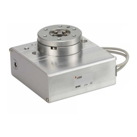
PRODUCT NAME
Electric Rotary Table
MODEL / Series / Product Number
LER Series
<Controller>
LEC Series
This manual describes the actuators operation in combination with the LEC*6 series controllers.
Refer to the manual relevant to the controller being used for full operating instructions.
Advertisement
Table of Contents

Related Manuals for SMC Networks LER Series


Summary of Contents for SMC Networks LER Series
- Page 1 Doc. no. LER0-OM00303 PRODUCT NAME Electric Rotary Table MODEL / Series / Product Number LER Series <Controller> LEC Series This manual describes the actuators operation in combination with the LEC*6 series controllers. Refer to the manual relevant to the controller being used for full operating instructions.
-
Page 2: Table Of Contents
2.1 LER Series( Basic ・ External stopper ) ......10 2.1.1 Specification ..........................10 2.1.2 How to Order..........................11 2.1.3 Construction ..........................12 2.2 LER Series( Continuous rotation / 360° type ) ....14 2.2.1 Specification ..........................14 2.2.2 How to Order..........................15 2.2.3 Construction ..........................16 3. - Page 3 7. Troubleshooting ................42 - 2 –...
-
Page 4: Safety Instructions
LER Series/Electric Rotary Table Safety Instructions These safety instructions are intended to prevent hazardous situations and/or equipment damage. These instructions indicate the level of potential hazard with the labels of “Caution,” “Warning” or “Danger.” They are all important notes for safety and must be followed in addition to International Standards (ISO/IEC), Japan Industrial Standards (JIS)*1) and other safety regulations*2). - Page 5 LER Series/Electric Rotary Table Safety Instructions Caution The product is provided for use in manufacturing industries. The product herein described is basically provided for peaceful use in manufacturing industries. If considering using the product in other industries, consult SMC beforehand and exchange specifications or a contract if necessary.
-
Page 6: Procedure Before Operation/Simple Setting To Use Straight Away
1. Procedure before operation/simple setting to use straight away The controller is already set with the data of the actuator. With the simple setting “easy mode”, it can be operated and running parameters can be changed easily. 1.1 Preparation (1) Items to be prepared Please check on the label, and the quantity of accessories, to confirm that it is the product that was ordered. -
Page 7: Controller Setting Software Version
1.2 Controller setting software version (1) Installation of software With the controller setting software CD-ROM, install the communication unit software, following the “Software Installation procedure” (PDF) ※ When the controller setting software/version is below 1.1, the display unit is distance (mm), but the product recognizes it as an angle(°). - Page 8 (4) TEST Drive / Step No.0 → No.1 → No.0・・・ a. Driving preparation : Servo On → Return to ORIG / Refer to “3.JOG Drive”. b.TEST Drive “Step No.0” Operation Procedure 2: → Operation Procedure 1: Select “Drive” Select “Step No.0” You can select anywhere in the row “Step No.1”...
-
Page 9: Teaching Box
1.3 Teaching box (1) Name (2) JOG key (3)SET key (4) Up and down, right and left key (5)MENU key (1) Number key (2) JOG Drive データ テスト モニタ EXT Inp OFF:YES Operates by (2) JOG key DATA TEST MONITOR JOG+: “S”... - Page 10 (4) Step data change “Step No.0” / Positioning operation データ テスト モニタ Screen showing the Change of positioning DATA MONITOR TEST actuator speed.of speed → 50 °/s °/s °/s Speed 200 アラーム ジョグ 設定 ALARM SETTING Step Step Step No. Step No.
-
Page 11: Electric Rotary Table /Ler Series
2. Electric Rotary Table /LER Series 2.1 LER Series( Basic ・ External stopper ) 2.1.1 Specification Model LER*10K LER*10J LER*30K LER*30J LER*50K LER*50J Rotation Angle (°) Gear rate(°) Max. Rotation Torque(N・m) 0.32 0.22 10.0 Note 1) Note 3) Pushing Torque 40~50%(N・m) 0.13~0.16... -
Page 12: How To Order
2.1.2 How to Order Caution The actuator body and controller are sold as a package. If When only the actuator is purchased separately, confirm that the combination of the controller, which you have and the actuator is compatible. / See 5.3 Caution (1) on p. -
Page 13: Construction
2.1.3 Construction Manual override /Both sides High precision Basic Parts list Part Material Remarks Body Aluminium alloy Anodized Side plate A Aluminium alloy Anodized Side plate B Aluminium alloy Anodized Heat treated, Worm screw Stainless steel Specially treated Heat treated, Worm wheel Stainless steel Specially treated... - Page 14 External stopper Parts list Part Material Remarks Table Aluminium alloy Anodized Carbon steel Nickel plated Holder Aluminium alloy Anodized Adjustment bolt Carbon steel Chromating - 13 -...
-
Page 15: 2.2 Ler Series
2.2 LER Series( Continuous rotation / 360° type ) 2.2.1 Specification Model LER*10K LER*10J LER*30K LER*30J LER*50K LER*50J ) Note 9) Rotation Angle (°) Note 9) Angle range (°) ±20000000 Max. Rotation Torque(N・m) 0.32 0.22 10.0 Note 1) Note 3) Pushing Torque 40~50%(N・m) -
Page 16: How To Order
2.2.2 How to Order Caution The actuator body and controller are sold as a package. If When only the actuator is purchased separately, confirm that the combination of the controller, which you have and the actuator is compatible. / See 5.3 Caution (1) on p. -
Page 17: Construction
2.2.3 Construction Manual override /Both sides High precision Basic Parts list Part Material Remarks Body Aluminium alloy Anodized Side plate A Aluminium alloy Anodized Side plate B Aluminium alloy Anodized Heat treated, Worm screw Stainless steel Specially treated Heat treated, Worm wheel Stainless steel Specially treated... -
Page 18: Product Outline
3. Product Outline 3.1 System construction Note 1) ●I/O cable ●Electric Rotary Table Part No:LEC-CN5- Note 1) Motor cable ●Controller Note 2) Power supply DC24V To CN5 Option Communication To CN4 Note 1) cable To CN4 ●Actuator cable Controller setting To CN3 Part No: software... -
Page 19: Setting Function
3.2 Setting Function Refer to the operation manual of the cotroller (LEC series) for details of the setting function. Easy Mode for simple setting >Select “Easy mode” for instant operation Controller setting software Setting and operation, such as the step data setting, test drive and JOG / fixed-distance moving, can be performed on the same page. - Page 20 Normal mode for the detailed setting >Select “Normal mode” if the detailed setting are necessary. Step data can be set in detail. Parameters can be set. Signals and terminal condition can be monitored. JOG and fixed distance movement, return to origin position, test operation and testing of compulsory output can be done.
- Page 21 Controlled items PC: Controllersetting sftware TB: Teaching box O: Available function X: Not available function Easy Normal mode mode Function Content PC/TB ○ ○ Movement method Can be selected of absolute / relative position move × ○ ○ ○ Speed Can be set in units of 1°/s.
-
Page 22: Step Data Setting Method
3.3 Step data setting method Refer to the operation manual of the controller (LEC series) for details. This operation manual specifies the electric rotary actuator, if an actuator other than the electric rotary actuator is used, refer to the operation manual of each type of actuator and controller (LEC series) regarding the description of step data. - Page 23 <Items and set values in positioning operation> Step No. 0: Positioning operation 【◎】 Need to be set ・ 【○】Need to be adjusted as required 【X】 Not used. Items don't need to be changed in positioning operation. a <◎ Movement MOD> When the absolute position is required, set Absolute When the relative position is required, set Relative ⇒...
-
Page 24: Pushing Operation
Pushing operation The table move to the target position and hold a work piece with the set pushing force. The figure shows setting items and operation.The setting items and values are described below. < Confirmation of reaching the target value during the pushing operation> The “target position reaching signal”... - Page 25 <Items and setting values of pushing operation> Step no. 1: Pushing operation 【◎】 Need to be set ・ 【○】Need to be adjusted as required a <◎ Movement MOD> When the absolute position is required, set Absolute When the relative position is required, set Relative ⇒...
- Page 26 Example of step data entry (1) < Positioning operation - 【INP】output signal, 【AREA】output signal > ・Step data no.0 : Positioning operation (It moves from Position:180[°] to Position:0[°]) Condition 1) The 【AREA】output signal is not used. P osi t i on[ ° ] 90°...
- Page 27 Example of step data entry (2) < Pushing operation - 【INP】output signal, 【AREA】output signal > ・Step data no.0 : Positioning operation. (It moves to End limit after it moves from 180° to 40°.) Condition 1) The 【AREA】output signal is not used. I n pos[ °...
- Page 28 Example of step data entry (3) < Pushing operation - In position > ・Step data no.0 : Pushing operation ("Pushing operation" is done during 40° after it moves from 100° to 60°.) Condition 1) Length to work < In position 60°...
- Page 29 Example of step data entry (4) < Pushing operation – Driving starting position > The pushing action is different and dependent upon the starting position and derection. Confirm the position where the pushing operation starts. Move M Speed Position Accel Decel PushingF TriggerLV PushingSp MovingF...
-
Page 30: Operating Procedure And Input / Output Signals For Each Operation
Operating procedure and input / output signals for each operation. The input / output signal and the operation description for operating this electric actuator are as follows. 1) Signals along with the operation procedures In case the operation order is 1. -
Page 31: Continuous Rotation / 360° Type Setting
2) Signals when stopped: In the event when “EMG” is used The operating sequence is 1. “Stop” 2. Release the “Stop” Output signal for the input Procedure Input signal Operation description signal Power to the motor is cut by the *ESTOP[ “Stop “... -
Page 32: Parameter Setting Method
3.4 Parameter setting method Initial setting for the basic parameters Refer to the controller’s (LEC series) operation manual for detail. As the “basic parameter” is unique data of each actuator, if an actuator other than the rotary actuator is used, refer to the operation manual of each actuator and the controller’s (LEC series) operation manual for the basic parameter. -
Page 33: Initial Setting For The Orig Parameters
Initial setting for the ORIG parameters Refer to the controller’s (LEC series) operation manual for detail. As the “ORIG parameter” is unique data of each actuator, if an actuator other than the electric rotary actuator is used, refer to the operation manual of each actuator and the controller’s (LEC series) operation manual for the for the “ORIG parameters”... -
Page 34: Wiring Of Cables / Common Precautions
4. Wiring of cables / Common precautions Warning Adjusting, mounting or wiring change should never be done before shutting off the power supply to the product. Electrical shock, malfunction and damaged can result. Never disassemble the cable. Use only specified cables. Never connect or disconnect the cable or connector with power on. -
Page 35: Electric Actuators / Common Precautions
5. Electric actuators / Common precautions 5.1 Design and selection Warning 1. Be sure to read the Operation Manual (this manual and the one for the controller: LEC series). Handling or usage/operation other than that specified in the Operation Manual may lead to breakage and operation failure of the product. -
Page 36: Mounting
Rerutning to origin cannot be done during the operation. It cannot be done during positioning operation, pushing operation and pushing. Refer to a common auto switch /matter (Best Pneumatics No 2) when an auto switch is built in and used. When conformity to UL is required, the electric actuator and controller should be used with a UL1310 Class 2 power supply. -
Page 37: Handling
5.3 Handling Warning Do not touch the motor while in operation. The surface temperature of the motor can increase to approx. 80 C due to operating conditions. Energizing alone may also cause this temperature increase. As it may cause burns, do not touch the motor when in operation. -
Page 38: Operating Environment
[Unpackaging] Caution 1. Check the received product is as ordered. If the different product is installed from the one ordered, injury or damage can result. 5.4 Operating environment Warning 1. Avoid use in the following environments. a. Locations where a large amount of dusts and cutting chips are airborne. b. -
Page 39: Maintenance
5.5 Maintenance Warning Do not disassemble or repair the product. Fire or electric shock can result. Contact SMC, in case of disassembly for the maintenance. Before modifying or checking the wiring, the voltage should be checked with a tester 5 minutes after the power supply is turned off. -
Page 40: Electric Rotary Table /Specific Product Precautions
6. Electric Rotary Table /Specific Product Precautions 6.1 Design and selection Warning If the operating conditions involve load fluctuations, ascending/descending movements, or changes in the frictional resistance, ensure that safety measures are in place to prevent injury to the operator or damage to the equipment Failure to provide such measures could accelerate the operating speed, which may be hazardous to humans, machinery, and other equipment. -
Page 41: Handling
Rotary actuator mounting (tapped holes) Max. Max. thread Part no. Bolt tightening depth L[mm] torque [Nm] LER*10 M6×1 LER*30 M8×1.25 12.0 LER*50 M10×1.5 25.0 The mounting face has holes and slots for positioning. If required use them for accurate positioning of the rotary actuator. If it is necessary to operate the product when it is not energized, use the manual override screws. -
Page 42: Maintenance
When the load is tobe stopped by the product with an external stopper or an external object directly, utilize the “pushing operation”. Do not stop the table with an external object by positioning operation and in the range of the positioning operation. If the product is used in the positioning operation, there may be galling or other problems when it comes into contact with the external object. - Page 43 7. Troubleshooting Alarms below are abstract of representative examples. For other alarms, see operation manual of controller. Phenomenon Cause Countermeasure The display unit is distance (mm) When controller setting If it is necessary to change it to due to the controller setting software/version is below 1.1, the the angle display, please upgrade software.
- Page 44 Phenomenon Cause Countermeasure Operation not completed 1) The lead screw had galling due Operate within the specified range / Operation continue to excessive external force /See Specifications on p10,p14 (including vibration) or impact. Release the warm using the Alarm for “Posn failed manual override.
- Page 45 Phenomenon Cause Countermeasure Alarm for “Pushing ALM 1) For the pushing operation, the Check the step data. Caution /code: 1-096” is generated. position, target start-pushing /See 6.3 (5) on p.41 ↓ position, is not set correctly. 2) It was not intended origin <Procedure of restart>...
- Page 46 Phenomenon Cause Countermeasure Alarm for “ Err overflow 8) Wrong input [0] is input as the Check the step data. /code: 1-196” is generated. positioning force. <Moving force> ↓ /See “Step data setting” on p.22,24 <Procedure of restart> 9) The step data position has not Check the step data.
- Page 47 Phenomenon Cause Countermeasure “INP” output signal is unstable. 1) The value of [In position] in Check the step data. <In Pos> step data is too small. Positioning completion signal [INP] (Minimum value:0.5) /See “Step data setting” on p.22 is not outputted. “INP”...
- Page 48 Revision history No.LER-OM00201 Feb / 2011 1st printing No.LER-OM00202 Mar / 2011 Revision No.LER-OM00203 Apr / 2012 Revision ・Addition / Notes about UL recognition. No.LER-OM00204 Feb / 2013 Revision ・Addition / LER*-1 Series. (360°Type) No.LER-OM00205 Apr / 2013 Revision No.LER-OM00206 Nov / 2013 Revision ・How to Order ・Change of specification...
Need help?
Do you have a question about the LER Series and is the answer not in the manual?
Questions and answers