Table of Contents
Advertisement
Quick Links
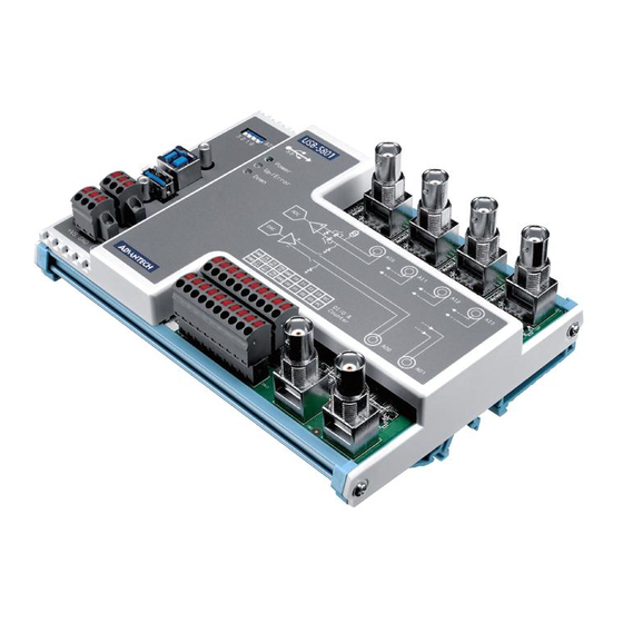
USB-5801
4-Ch, 24-Bit, 192 kS/s Dynamic Signal Acquisition USB
3.0 I/O Module with Analog Output and Tachometer
Startup Manual
Packing List
Before installation, please ensure that the following items
are included with the product:
• 1 x USB-5801 module
• 4 x Terminal blocks
• 1 x USB 3.0 lockable cable (1 m)
• 1 x USB-5801 startup manual
If any of the above items are missing or damaged, contact
your distributor or sales representative immediately
User Manual
For more detailed information regarding this product, please
download the USB-5801 user manual from the Advantech
website.
Overview
USB-5801 is a highly accurate dynamic signal acquisition
USB 3.0 module specifically designed for vibration and
acoustic measurements. The module provides four simulta-
neously sampled 24-bit IEPE sensor inputs with an up to 192
kS/s sample rate for high-resolution measurements. USB-
5801 is also equipped with two 24-bit analog outputs with an
up to 192 kS/s update rate and two tachometer inputs whose
data can be correlated to the sensor data. The built-in USB
hub makes this module daisy chainable with other USB-5000
series products.
For more information about this or other Advantech
products, visit our website at
http://www.advantech.com
For technical support and customer service, visit our
support website at
http://support.advantech.com
This manual is for USB-5801.
Part No. 2041580101
Printed in China
Declaration of Conformity
FCC Class A
This equipment has been tested and found to comply with
the limits for a Class A digital device, pursuant to part 15
of the FCC rules. These limits are designed to provide rea-
sonable protection against harmful interference when the
equipment is operated in a commercial environment. This
equipment generates, uses, and can radiate radio frequency
energy and, if not installed and used in accordance with the
instruction manual, may cause harmful interference to radio
communications. Operation of this equipment in a residential
area is likely to cause interference. In such cases, users are
required to correct the interference at their own expense.
CE
This product has passed the CE test for environmental speci-
fications when shielded cables are used for external wiring.
We recommend the use of shielded cables. This kind of cable
is available from Advantech. Please contact your local sup-
plier for ordering information.
Specifications
Analog Input
• Channels: 4 (simultaneous sampling, 50 Ω pseudo
differential configurable)
• Resolution: 24 bits (delta-sigma ADC)
• Max. Sampling Rate: 1 ~ 192 kS/s
• Input Coupling: AC/DC, selectable per channel
• Trigger Mode: Start, delay start, stop, delay stop
• Input Range: ±1 V, ±2 V, ±5 V, ±10 V
• Offset Error: < ±0.2 mV
• Gain Error:< ±0.02% of full-scale range
• Total Harmonic Distortion Plus Noise (THD+N): -95 dB
• IEPE Excitation: 2 mA
• Automatic Calibration: Yes
Analog Output
• Channels: 2 (50 Ω pseudo differential)
• Resolution: 24 bits (delta-sigma DAC)
• Update Rate: 1 ~ 192 kS/s
• Output Coupling: DC
• Output Range: ±1 V, ±10 V
• Offset Error: < ±0.5 mV
• Gain Error: < ±0.03% of full-scale range
Edition 2
May 2019
USB-5801 Startup Manual 1
Advertisement
Table of Contents

Subscribe to Our Youtube Channel
Related Manuals for Advantech USB-5801


Summary of Contents for Advantech USB-5801
- Page 1 In such cases, users are For more detailed information regarding this product, please required to correct the interference at their own expense. download the USB-5801 user manual from the Advantech website. This product has passed the CE test for environmental speci- fications when shielded cables are used for external wiring.
- Page 2 • Trigger Mode: Start, delay start, stop, delay stop • Automatic Calibration: Yes The Advantech DAQNavi Device Drivers setup program for the USB-5801 module can be downloaded from the Tachometer Input Advantech website (www.advantech.com). Follow the steps outlined below to install the driver software.
- Page 3 Block Diagram Connector, Switch, and LED Locations USB-5801 Startup Manual 3...
- Page 4 USB upstream port (USB 3.0 type-B connector with screw). Connect this port to the host or the down- stream port of the previous USB module. USB downstream port (USB 3.0 type-A connector with screw). Connect this port to the upstream port of the next USB module, if any. 4 USB-5801 Startup Manual...
- Page 5 Ground for digital signals Connector Pin Name Description CN12 & External 10 ~ 30 V power supply CN13 Power ground Chassis ground Note: CN12 and CN13 are used for power redundancy. External power can be supplied by either connector. USB-5801 Startup Manual 5...
- Page 6 Sensor is connected to analog input channel 3 and works normally Sensor connected to analog input channel 3 is short circuited Note: LEDs near CN4 ~ CN7 function only when IEPE is enabled for the corresponding analog input channel. 6 USB-5801 Startup Manual...
Need help?
Do you have a question about the USB-5801 and is the answer not in the manual?
Questions and answers