
Related Manuals for Advantech USB-5801


Summary of Contents for Advantech USB-5801
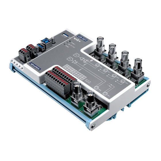
- Page 1 User Manual USB-5801 4-CH, 24-Bit, 192 kS/s Dynamic Signal Acquisition USB 3.0 I/O Module with Analog Output and Tachometer...
- Page 2 This documentation and the software included with this product are copyrighted 2019 by Advantech Co., Ltd. All rights are reserved. Advantech Co., Ltd. reserves the right to improve the products described in this manual at any time without notice. No part of this manual may be reproduced, copied, translated, or transmitted in any form or by any means without the prior written permission of Advantech Co., Ltd.
- Page 3 This product has passed the CE test for environmental specifications when shielded cables are used for external wiring. We recommend the use of shielded cables. This type of cable is available from Advantech. Please contact your local supplier for ordering information.
- Page 4 USB-5801 User Manual...
-
Page 5: Table Of Contents
Chapter Installation..........7 Unpacking Instructions................8 Driver Installation ..................9 Figure 2.1 Advantech DAQNavi Installation Wizard ....9 Figure 2.2 Driver Installation Setup Screen ....... 10 Figure 2.3 Driver Installation Path and Space Requirements..10 Figure 2.4 Driver Installation Process........11 Figure 2.5 Exit the Driver Installation Wizard...... - Page 6 A.1.13 Spurious Free Dynamic Range (SFDR) ........42 A.1.14 Signal-to-Noise Ratio (SNR)............43 A.1.15 Total Harmonic Distortion (THD) ..........43 A.1.16 Total Harmonic Distortion Plus Noise (THD+N) ......43 A.1.17 Crosstalk..................43 A.1.18 Integrated Electronic Piezoelectric Excitation (IEPE) ....44 USB-5801 User Manual...
- Page 7 Tachometer ..................... 46 Digital I/O ....................47 A.5.1 Digital Input ................. 47 A.5.2 Digital Output ................47 General Specifications ................48 A.6.1 Bus Interface................48 A.6.2 Power Requirements ..............48 A.6.3 Physical..................48 A.6.4 Environmental ................48 USB-5801 User Manual...
- Page 8 USB-5801 User Manual viii...
-
Page 9: Chapter 1 Introduction
Chapter Introduction This chapter provides an intro- duction to USB-5801 and its typi- cal applications. Features Applications Installation Guide Software Overview Accessories... -
Page 10: Features
USB-5801 is a high accuracy dynamic signal acquisition USB 3.0 module specifically designed for vibration and acoustic measurements. It provides four simultaneously sampled, 24-bit, IEPE sensor inputs with up to 192 kS/s sample rate for high resolu- tion measurements. It is also equipped with two 24-bit analog outputs with up to 192 kS/s update rate. -
Page 11: Installation Guide
Board ID Switch USB-5801 modules have a built-in DIP switch that is used to define the board ID for each module. When multiple modules are installed in the same system, the board ID switch can be used to identify each module’s device number. -
Page 12: Figure 1.1 Installation Flowchart
Figure 1.1 Installation Flowchart USB-5801 User Manual... -
Page 13: Software Overview
Software Overview Advantech offers a wide range of DLL drivers, third-party drivers, and application software for fully exploiting the functions of your USB-5801 module. Device Drivers Advantech DAQNavi DAQNavi Software Advantech’s DAQNavi software includes device drivers and a software development kit (SDK), which features a comprehensive I/O function library to boost application performance. -
Page 14: Accessories
Programming with DAQNavi Device Drivers Function Library Advantech offers a comprehensive function library for DAQNavi device drivers that can be utilized when developing various application programs. This function library comprises numerous APIs that support many development tools, such as Visual Stu- dio.NET, Visual C++, Visual Basic, Delphi and C++ Builder. -
Page 15: Chapter 2 Installation
Chapter Installation This chapter includes a packing checklist, instructions for unpack- ing, and step-by-step procedures for both driver and card installa- tion. Unpacking Instructions Driver Installation Hardware Installation Device Setup and Configuration... -
Page 16: Unpacking Instructions
Unpacking Instructions After receiving your USB-5801 module, inspect the package contents to ensure that the following items are present: 1 x USB-5801 module 4 x terminal blocks 1 x USB-5801 startup manual 1 x USB 3.0 lockable cable (1 m) The USB-5801 module contains electronic components that are vulnerable to elec- trostatic discharge (ESD). -
Page 17: Driver Installation
Driver Installation We recommend installing the drivers before installing the USB-5801 module to guar- antee a problem-free installation process. The Advantech DAQNavi Device Drivers setup program can be downloaded from the Advantech website. Follow the steps outlined below to install the driver software. -
Page 18: Figure 2.2 Driver Installation Setup Screen
Figure 2.2 Driver Installation Setup Screen Once the DAQNavi driver installation wizard is launched, follow the instructions displayed in the interface to complete the driver installation. Figure 2.3 Driver Installation Path and Space Requirements USB-5801 User Manual... -
Page 19: Figure 2.4 Driver Installation Process
Figure 2.4 Driver Installation Process After the driver is successfully installed, click the “Finish” button to exit the instal- lation wizard. Figure 2.5 Exit the Driver Installation Wizard USB-5801 User Manual... -
Page 20: Hardware Installation
Ensure that the relevant driver is installed before installing the USB-5801 mod- ule. (Refer to Section 2.2 “Driver Installation” for more information.) After the device drivers are installed, the USB-5801 module can be installed in your computer. We recommend referring to the computer user manual or related docu- mentation if you have any concerns. -
Page 21: Device Setup And Configuration
Device Setup and Configuration The Advantech Navigator program is a utility for setting up, configuring, and testing devices. The program also stores the system configuration settings in the system registry for subsequent reference. These settings are used when a device driver API is called. - Page 22 Configuring the Device Go to the Device Setting page to configure the device. The items in the page allow users to configure the USB-5801 modules’ analog input. Figure 2.7 Device Settings Page After the module is installed and configured, access the Device Testing page to test the hardware using the test utility provided.
-
Page 23: Chapter 3 Signal Connections
Chapter Signal Connections This chapter explains how to con- nect input and output signals to the USB-5801 module via the I/O connector. Overview Board ID Settings Signal Connections Field Wiring Considerations... -
Page 24: Overview
A good signal con- nection can prevent unnecessary and costly damage to your PC and other hardware devices. This chapter provides information about connecting input and output signals to the USB-5800 module via the I/O connector. Dimensions USB-5801 User Manual... -
Page 25: Connector, Switch, And Led
Negative terminal of analog input channel 3 Center pin Positive terminal of analog output channel 0 Outer shield Negative terminal of analog output channel 0 Center pin Positive terminal of analog output channel 1 Outer shield Negative terminal of analog output channel 1 USB-5801 User Manual... - Page 26 Initial state. Module has not been connected Upstream port is connected. Module is functioning nor- Green LED3 mally Upstream port is not connected or is disconnected. Mod- ule function is halted Downstream port is not connected LED4 Blue Downstream port is connected USB-5801 User Manual...
- Page 27 Sensor is connected to analog input channel 3 and Near CN7 Green works normally Sensor connected to analog input channel 3 is short cir- cuited Note! LEDs near CN4 ~ CN7 are functioning only when IEPE is enabled for the corresponding analog input channel. USB-5801 User Manual...
-
Page 28: Analog Input
The pseudo-differential configuration provides a ground reference between the floating source and the USB-5801 by connecting a 50 Ω resistor from the nega- tive input to ground. This is shown in Figure 3.2. Without this, the floating source can drift outside of the input common-mode range of the USB-5801. -
Page 29: Analog Input Coupling
There is no settling time issue when switching the analog input channels from AC coupling to DC coupling. The high-pass RC filter for AC coupling will attenuate the low-frequency component of the input signal. The -3 dB cut-off frequency is 0.796 Hz. USB-5801 User Manual... -
Page 30: Integrated Electronic Piezoelectric (Iepe) Excitation
3.4.4 Integrated Electronic Piezoelectric (IEPE) Excitation The USB-5801 is equipped with a 2 mA constant current source of IEPE excitation for each analog input channel. When an IEPE sensor such as accelerometer or microphone is connected to the analog input terminals, the IEPE excitation for that channel must be enabled. -
Page 31: Analog Input Ranges
3.4.5 Analog Input Ranges The USB-5801 supports 4 different analog input ranges: ±10 V, ±5 V, ±2 V, and ±1 V. Users should select the input range that is large enough for all possible voltage val- ues of the input signal, and small enough to make full use of the input dynamic range. -
Page 32: Analog Input Measurement Types
Analog Output 3.5.1 Analog Output Overview The USB-5801 provides 2 channels of analog output (AO) signal measurement. Fig- ure 3.7 shows the functional block diagram of one analog input channel. Figure 3.7 Analog Output Functional Block Diagram The DAC generates single-ended analog output signals. The single-ended signal is converted to differential signal by a buffer, and then goes through a low-pass interpo- lating filtered to a BNC connector. -
Page 33: Analog Output Loads
3.5.3 Analog Output Loads Although the USB-5801 is specified to drive a minimal load of 600 Ω, the output sig- nal distortion is minimized for high impedance load. Users can, for example, connect the analog outputs to external devices with larger input impedance such as 10 kΩ or 100 kΩ... -
Page 34: Trigger
Trigger 3.6.1 Trigger Functions Data acquisition or generation of the USB-5801 is controlled by the start trigger and the stop trigger. The returned data consists of samples acquired after the start trigger occurs and before the stop trigger occurs. Both the start and stop triggers can be delayed by a predefined delay sample num- ber. -
Page 35: Analog Triggers
±10 V input range as analog trigger source, a 0.1% hysteresis range equals to 20 mV. Figure 3.14 shows examples of both rising edge and falling edge analog trig- ger with hysteresis. Figure 3.12 Analog Triggers with Hysteresis USB-5801 User Manual... -
Page 36: Analog Calibration
3.7.1 Analog Calibration Overview USB-5801 implements a specially designed circuitry for analog calibration. By select- ing different calibration sources, each component of the analog functions can be cali- brated individually. In addition, the calibration parameter is stored in an electrically- erasable programmable read-only memory (EEPROM). -
Page 37: Voltage References Calibration
Repeat this step until the DMM reading is within the voltage range specified by "target voltage". Repeat steps 2 through 3 for all voltage references. Figure 3.14 Voltage Reference Calibration USB-5801 User Manual... -
Page 38: Analog Input Calibration
In the Navigator, select "AI Calibration", click "Start" button, and wait for calibration finished. Figure 3.15 Analog Input Calibration 3.7.4 Analog Output Calibration In the Navigator, select "AO Calibration", click "Start" button, and wait for calibration finished. Figure 3.16 Analog Output Calibration USB-5801 User Manual... -
Page 39: Store Calibration Parameters To Eeprom
To prevent from losing those parameters after powering off, it is required to store them in a non-volatile memory such as an EEPROM. Figure 3.17 Store Calibration Parameters to EEPROM USB-5801 User Manual... -
Page 40: Load Default Calibration Parameters From Eeprom
EEPROM by clicking "Load Default" button if needed. Note that this operation only loads the parameters into the on-board volatile memory. To keep them permanently, it is required to store them into the EEPROM by clicking "Save All" button. Figure 3.18 Load Default Calibration Parameters from EEPROM USB-5801 User Manual... -
Page 41: Digital Input/Output
Digital Input/Output 3.8.1 Digital Inputs The USB-5801 provides 4 channels of digital input (DI) signal measurement with 2,500 V galvanic isolation. Figure 3.21 shows the functional block diagram of one digital input channel. Figure 3.19 Digital Input Functional Block Diagram When an external voltage (V in Figure 3.21) is applied to the digital input between... -
Page 42: Figure 3.21Digital Input Filter
This is shown in Figure 3.23. Digital input filter can be enabled/disabled and filter duration can be configured independently for each channel. Figure 3.21 Digital Input Filter USB-5801 User Manual... -
Page 43: Digital Outputs
(VEX), and the ground of the external source should be connected to the ground of the USB-5801. When the digital output is on, the MOSFET on the USB-5801 closes and provides a path for the load current flowing through to the ground. When the digital output is off, on the other hand, the MOSFET opens and blocks the path. -
Page 44: Event Counting
FIFO. By subtracting consecutive two counter values (TCA and TCB), the period or the frequency of the signal can be cal- culated as shown in the following equations. A frequency measurement example is shown in Figure 3.27. Figure 3.25 Frequency Measurement USB-5801 User Manual... -
Page 45: Phase Measurement For Analog Input Samples
For example, to calculate the phase of the 1.5 V analog input sample (the second sample) in Figure 3.28, first find the corresponding PC, which is 1005. Then find the TCA and TCB, which are 1000 and 2000, respectively. Use the previous equation, the phase of the 1.5 V analog input sample can be calculated as 1.8°. USB-5801 User Manual... -
Page 46: Synchronization
3.10 Synchronization Multiple USB-5801 modules can be synchronized to support more acquisition chan- nels. Each module has one trigger input pin (TRGIN) and one trigger output pin (TRGOUT). To synchronize multiple modules, users must choose one of the modules to be the trigger master, and others as trigger slaves. Connect TRGOUT pin of the... -
Page 47: Appendix A Specifications
Appendix Specifications... -
Page 48: Analog Input
Pseudo-differential ±12 V ±9 V Enabled Pseudo-differential 0 ~ +24 V 0 ~ +1 V * Voltages with respect to chassis ground. Note: Input coupling must be AC and input configuration must be pseudo-differential when IEPE is enabled. USB-5801 User Manual... -
Page 49: Input Overvoltage Protection
Between Positive Terminal (+) Between Negative Terminal (-) Input Configuration and Chassis Ground and Chassis Ground Differential 200 kΩ 200 kΩ Pseudo-Differential 200 kΩ 50 Ω A.1.8 Common-Mode Rejection Ratio (CMRR) Input Frequency < 20 kHz: 60 dB USB-5801 User Manual... -
Page 50: Frequency Response
Spurious Free Dynamic Range (dBc)*,** Input Range = 32 kS/s = 128 kS/s = 192 kS/s ±10.0 V ±5.0 V ±2.0 V ±1.0 V * 1 kHz input tone, input amplitude is -1 dBFS. ** Measurement includes all harmonics. USB-5801 User Manual... -
Page 51: Signal-To-Noise Ratio (Snr)
* 1 kHz input tone, input amplitude is -1 dBFS. A.1.17Crosstalk Crosstalk (dBc)* Input Range 32 kS/s 192 kS/s = 1 kHz = 20 kHz ±10.0 V -104 -100 ±5.0 V -104 -100 ±2.0 V -104 ±1.0 V -103 * Input amplitude is -1 dBFS. USB-5801 User Manual... -
Page 52: Integrated Electronic Piezoelectric Excitation (Iepe)
Operating temperature within 5 °C of last auto-calibration temperature: < ±0.5 mV Over full operating temperature range: < ±2.5 mV A.2.3 Output Noise = 32 kS/s = 128 kS/s = 192 kS/s Output Range μV μV μV ±10.0 V/±1.0 V 70.7 70.2 60.7 USB-5801 User Manual... -
Page 53: Spurious Free Dynamic Range (Sfdr)
Total Harmonic Distortion Plus Noise (THD+N) Total Harmonic Distortion Plus Noise (dB)* Output Range = 32 kS/s = 128 kS/s = 192 kS/s ±10.0 V ±1.0 V * 1 kHz output tone, output amplitude is -1 dBFS. USB-5801 User Manual... -
Page 54: Triggers
Input Voltage (referenced to GND pin) Logic 0 < +3 V (-30 V min.) Logic 1 > +10 V (+30 V max.) Input Frequency 5 kHz max. Digital Filter 16 μs ~ 131 ms 2,500 V Isolation Protection USB-5801 User Manual... -
Page 55: Digital I/O
16 μs ~ 131 ms 2,500 V Isolation Protection A.5.2 Digital Output Channels Load Voltage 5 ~ 40 V (referenced to GND pin) Load Current 350 mA/ch (sink) Opto-Isolator Response Time 100 μs 2,500 V Isolation Protection USB-5801 User Manual... -
Page 56: General Specifications
Operating Temperature 0 to 60 °C (32 to 140 °F) Storage Temperature -40 to 70 °C (-40 to 158 °F) Operating Humidity 10 to 90% RH, non-condensing Storage Humidity 5 to 95% RH, non-condensing Indoor Use Only. USB-5801 User Manual... - Page 57 USB-5801 User Manual...
- Page 58 No part of this publication may be reproduced in any form or by any means, such as electronically, by photocopying, recording, or otherwise, without prior written permission from the publisher. All brand and product names are trademarks or registered trademarks of their respective companies. © Advantech Co., Ltd. 2019...
Need help?
Do you have a question about the USB-5801 and is the answer not in the manual?
Questions and answers