Festo SOPA Series Instructions Manual
Air gap sensor
Hide thumbs
Also See for SOPA Series:
- Operating instructions manual (80 pages) ,
- Operating instructions manual (84 pages)
Table of Contents
Advertisement
Quick Links
SOPA
Air gap sensor
Instructions | Operating
8118603
2019-12c
[8118605]
Translation of the original instructions
© 2020 all rights reserved to Festo SE & Co. KG
1
About this document
1.1
Purpose of the Document
This document describes the use of the above-mentioned product. Certain
aspects of use are described in other documents and must be observed
è 1.2 Applicable Documents.
1.2
Applicable Documents
All available documents for the product è www.festo.com/pk.
Document
Description of air gap sensor SOPA
IO-Link IODD
Tab. 1 Applicable Documents
2
Safety
2.1
General Safety Instructions
–
Only use the product in original status without unauthorised modifications.
–
Only use the product if it is in perfect technical condition.
–
Only use media in accordance with the specifications è Technical data.
–
Observe labelling on the product.
–
Note that changes to the switching status (EDIT mode) become effective
immediately.
2.2
Intended Use
The air gap sensor SOPA is intended for distance monitoring in a range of
20 ... 200 μm. The distance measurement is performed using a non-contact pneu-
matic measuring process. This enables it to be used in harsh ambient conditions.
2.3
Training of qualified personnel
Installation, commissioning, maintenance and disassembly should only be con-
ducted by qualified personnel.
2.4
UL/CSA Certification
In combination with the UL inspection mark on the product, the information in this
section must also be observed in order to comply with the certification conditions
of Underwriters Laboratories Inc. (UL) for USA and Canada.
UL/CSA Certification Information
Product category code
File number
Considered standards
UL mark
Tab. 2 UL/CSA Certification Information
This device is intended to be used with a Class 2 power source or Class 2 trans-
former in accordance with UL1310 or UL1585.
As an alternative a LV/C (Limited Voltage/Current) power source with one of the
following properties can be used:
–
This device shall be used with a suitable isolating source such that the max-
imum open circuit voltage potential available to the product is not more than
30 V DC and the current is limited to a value not exceeding 8 amperes meas-
ured after 1 minute of operation.
Festo SE & Co. KG
Ruiter Straße 82
73734 Esslingen
Germany
+49 711 347-0
www.festo.com
8118603
Contents
Functional description, installation, commission-
ing, maintenance, description of the IO-Link
parameters, technical data
Device Description File
NRNT2 (USA)
NRNT8 (Canada)
E253738
UL 508, 17th edition
C22.2 No. 14-2005
–
This device shall be used with a suitable isolating source in conjunction with
a fuse in accordance with UL248. The fuse shall be rated max. 3.3 A and be
installed in the 30 V DC power supply to the device in order to limit the avail-
able current.
3
Further information
–
Accessories è www.festo.com/catalogue.
–
Spare parts è www.festo.com/spareparts.
4
Service
Contact your regional Festo contact person if you have technical questions
è www.festo.com.
5
Product overview
5.1
Configuration
5.1.1
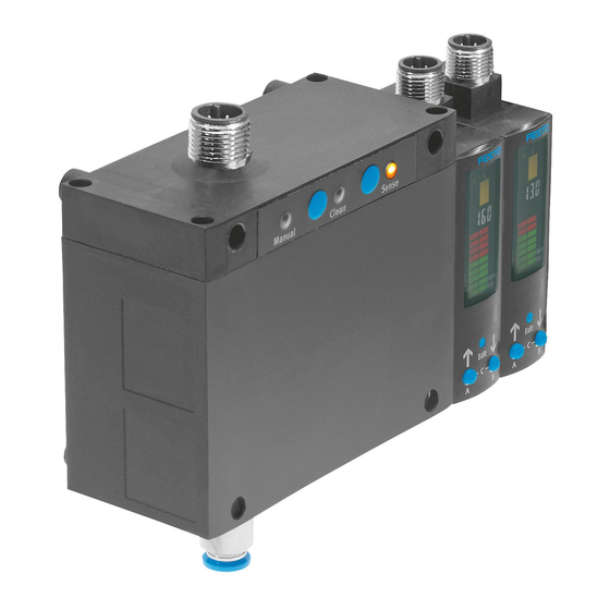
Product Design
1 Supply port for supply pressure
2 Sensor module (max. 4 modules
permitted in combination with con-
trol module)
3 Plug for the electrical connection
4 Display
5 Edit button
6 B pushbutton
7 A pushbutton
8 Label holder
9 Pneumatic connection for measur-
ing nozzle (output)
10 Supply port for operating pressure
11 Vent screw (width across flats 14)
Fig. 1 Product Design
5.1.2
Display Components
Fig. 2 LCD display
12 Fastening slides
13 Threaded sleeve (M4)
14 Blanking plug (M7)
15 Control module (optional)
16 Manual LED (green) – Ready indic-
ation for manual override (only
SOPA-C..-H)
17 Pushbutton - Clean (exhaust air)
(only SOPA-C..- H)
18 Status LED (yellow) – Clean
(exhaust air)
19 Pushbutton - Sense (measuring
air) (only SOPA-C..- H)
20 Status LED (yellow) – Sense
(instrument air)
1 Display of binary output OutA
2 Display of binary output OutB
3 Display of binary output OutC
4 4-digit alphanumeric display
5 Toolbar for functions
6 Bar graph
Advertisement
Table of Contents

Related Manuals for Festo SOPA Series


Summary of Contents for Festo SOPA Series
- Page 1 Accessories è www.festo.com/catalogue. Festo SE & Co. KG – Spare parts è www.festo.com/spareparts. Ruiter Straße 82 73734 Esslingen Service Germany Contact your regional Festo contact person if you have technical questions +49 711 347-0 è www.festo.com. www.festo.com Product overview Instructions | Operating Configuration 8118603 5.1.1...
-
Page 2: Pressure Regulator
5.1.2.1 Symbols on the Display Symbol Description Display of binary signals set/not set (in example A, B: set - C: not set) Threshold Value Comparator Window Comparator [SP] Switching point [SP][min] Lower switching point [SP][max] Upper switching point [HY] Hysteresis [NO] Switching characteristic of normally open contact [NC]... - Page 3 Assembling the Sensor Module (with Control Block max. 4) 1 Blanking plug 2 Threaded sleeve 1 Sensing variable 3 Binary signal 2 Input signal 4 Switching signal at sensor module plug Fig. 5 Binary signal, switching signal and analogue signal SOPA -...- PNLK -... Fig.
-
Page 4: Adapter Plate
6.2.3 Wall Mounting Electrical Installation WARNING! 1 Adapter plate Risk of injury due to electric shock. • For the electrical power supply, use only PELV circuits in accordance with IEC 60204-1/EN 60204-1 (Protective Extra-Low Voltage, PELV). • Observe the general requirements of IEC 60204-1/EN60204-1 for PELV cir- cuits. - Page 5 SOPA -...- PNLK Wire colour Allocation Plug Brown (BN) Operating voltage +24 V DC M12, 5-pin White (WH) Analogue output VB or A Blue (BU) Operating voltage 0 V Black (BK) Switching output for OutA or OutC (C/Q line with IO-Link) Grey (GY) n.c = free (not connected) 1) When using the connecting cable as per Accessories.
-
Page 6: Remove Device
Malfunctions 11.1 Fault Clearance Fault description Cause Remedy No indication on display Supply voltage not applied or Switch on the supply voltage; permitted operating voltage not observe the voltage range. present Electrical connections swapped Connect the sensor module in (incorrect polarity) accordance with the plug pat- tern. - Page 7 Disposal SOPA-... ENVIRONMENT! Short circuit current rating Send the packaging and product for environmentally sound recycling in accord- Overload protection Present ance with the current regulations è www.festo.com/sp. Tab. 25 Output, Additional Data Technical data SOPA-... 14.1 Technical Data, General -2P/-2N...
- Page 8 SOPA -...- PNLK-VB 0xC0 (192) – SOPA -...- PNLK-A 0xC1 (193) IODD, IO-Link® device description è www.festo.com/sp Fig. 21 Hole Patterns Tab. 32 IO-Link 14.2 Diagrams Response Times for Different Tube Lengths Fig. 17 Typical response time t as a function of distance x after switching on the...