Table of Contents
Advertisement
Advertisement
Table of Contents

Related Manuals for Festo SOPA-C series


Summary of Contents for Festo SOPA-C series
- Page 1 Air gap sensor SOPA-... Operating instructions 8078142 2017-09b [8068125]...
- Page 2 Text designations: • Activities that may be carried out in any order 1. Activities that should be carried out in the order stated – General lists è Result of an action/References to more detailed information Festo – SOPA-... – 2017-09b...
- Page 3 ............. Festo – SOPA-... – 2017-09b English...
- Page 4 ............Festo – SOPA-... – 2017-09b English...
-
Page 5: Product Description
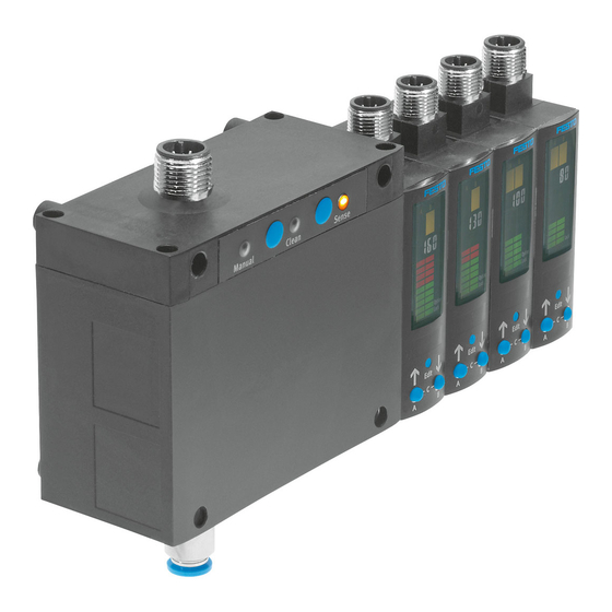
SOPA-... Product description For all available product documentation è www.festo.com/pk Overview Control module (optional) Threaded sleeve (M4) Sensor module (max. 4 modules permitted Blanking plug (M7) in combination with control module) Label holder Plug for electrical connection Adapter plate for wall mounting... - Page 6 B pushbutton Status LED (yellow) – Sense (instrument air) A pushbutton Status LED (yellow) – Clean (exhaust air) 1) Only for product variants with manual override (SOPA-C-...-H) Fig. 2 Operating elements and pneumatic connections Festo – SOPA-... – 2017-09b English...
-
Page 7: Features
Connecting cable with angled socket, cable length 2.5 m Connecting cable with angled socket, cable length 5 m 1) Optional manual override not selectable 2) Number of connecting cables dependent on the number of modules Tab. 1 Overview of variants Festo – SOPA-... – 2017-09b English... -
Page 8: Factory Settings
[Hy] Switching characteristic NO (normally open contact) [OutC] Lower switching point [SP min] 0.6 bar (60 kPa) Upper switching point [SP max] 1.8 bar (180 kPa) Switching characteristic NO (normally open contact) Tab. 2 Festo – SOPA-... – 2017-09b English... -
Page 9: Function And Application
The change in flow rate is detected by the sensor modules, converted into a distance-correlated value and displayed (speed measuring method with ejector). Festo – SOPA-... – 2017-09b English... -
Page 10: Operating Statuses
– Setting or alteration of the parameters for the air gap sensor (switching outputs, display). TEACH mode – Teaching-in of the switching points for the distance-correlated values (transfer of the current value as the trigger level). Tab. 3 SOPA operating statuses Festo – SOPA-... – 2017-09b English... -
Page 11: Function Range
– The switching point (SP) and hysteresis (HY) can be set for the binary signals Out A and Out B. Only the switching points can be adjusted for Out C. Festo – SOPA-... – 2017-09b English... - Page 12 – Lower reset point = switching point – hysteresis Range in which switching signals are Sensing distance suppressed in the event of fluctuations Measuring nozzle around the switching point (SP) Object Switching point Hysteresis Fig. 6 Sensing range with switching points Festo – SOPA-... – 2017-09b English...
-
Page 13: Graphic Distance Monitoring
Distance < 0.2 x switching point Is always lit up Status indicator 1) The switching point of Out A and Out B is between segment 5 and 6 Tab. 5 Bar graph in the RUN mode Festo – SOPA-... – 2017-09b English... -
Page 14: Spurious Pulse Suppression – Parameter Options
Min/max values The min/max values for supply pressure monitoring and distance monitoring can be displayed and reset in the SHOW mode è Chapter 5.5. Note Switching off the supply voltage resets the min/max values. Festo – SOPA-... – 2017-09b English... -
Page 15: Requirements For Product Use
• Take the ambient conditions at the location of use into consideration by means of suitable design measures – for example a suitable arrangement of the measuring nozzles. Festo – SOPA-... – 2017-09b English... - Page 16 • Observe the permissible tube lengths between the sensor module and measuring nozzle (è Technical Data, Chapter 11). Recessed measuring nozzle Exhaust Invalid Air duct (example) Measuring nozzle Distance 30 … 60 μm Fig. 8 Measuring nozzle configuration Festo – SOPA-... – 2017-09b English...
- Page 17 Note that, when more than one power supply or isolating device is used, connection in parallel is not permitted. UL approval information Product category code NRNT2 (USA) or NRNT8 (Canada) File number E253738 Considered standards UL 508, 17th edition, C22.2 No. 14-2005 UL mark Tab. 7 UL approval information Festo – SOPA-... – 2017-09b English...
-
Page 18: Installation
• According to the specified tube lengths (0.5 … 8 m). H-rail mounting: • Hang the SOPA on the H-rail and press it until the mounting tabs engage in place. Fig. 10 H-rail mounting Festo – SOPA-... – 2017-09b English... - Page 19 1. Mount the threaded M7 fitting onto the supply pressure connection 1 or 2. Max. thread length: 5.5 mm. 2. Seal the opposite connection with the M7 blanking plug. Spanner size AF 3 mm, tighten by hand. Fig. 13 Attaching sensor modules Festo – SOPA-... – 2017-09b English...
-
Page 20: Pneumatic System
Avoiding contamination of the measuring nozzles during downtimes The vent screw (è Fig. 2) can be removed and this connection used with a deactivated main air supply and power supply, if necessary, to feed purge air. Festo – SOPA-... – 2017-09b English... -
Page 21: Electrical Connection
Switch on signal input instrument air (Sense) Black (BK) n.c = free (not connected) Grey (GY) 1) Using the connecting cable from the electrical accessories è Chapter 1.2 Features Tab. 8 Pin allocation for control module Festo – SOPA-... – 2017-09b English... - Page 22 = free (not connected) Grey (GY) 1) Using the connecting cable from the electrical accessories è Chapter 1.2 Features Tab. 10 Pin allocation for sensor module Sensor module SOPA-...-...-...-2P-M12-... SOPA-...-...-...-2N-M12-... Tab. 11 Circuit diagrams for sensor module Festo – SOPA-... – 2017-09b English...
-
Page 23: Commissioning
– The bar graph for In A is always active. – The bar graph for In B is only active if the binary signal Out B is assigned to the switching output at Pin 2. Tab. 12 Symbols on the display Festo – SOPA-... – 2017-09b English... -
Page 24: Bar Graph On The Display
– 7-segment display shows the set option. Marked segments illuminate and – EDIT mode active. [Lock] flashes: – Special menu opens. – 7-segment display shows the security code. Tab. 13 Special bar graphs on the display Festo – SOPA-... – 2017-09b English... -
Page 25: Symbols For Representing The Menu Structure
Out A and/or Out B and – the signal statuses of the switching outputs Out A, Out B, Out C (set, not set). A flashing value indicates that the measuring range has been exceeded. Festo – SOPA-... – 2017-09b English... -
Page 26: Info/Show Mode
(è Technical Data, Chapter 11). 2. Switch on the operating voltage. The SOPA is in the RUN mode. 3. Check the SOPA settings (è Chapter 5.5). INFO/SHOW mode Fig. 15 Menu structure for the INFO mode/SHOW mode Festo – SOPA-... – 2017-09b English... - Page 27 If no other pushbuttons are pressed, this remains permanently on display (no timeout). The display of the minimum and maximum values can be reset by pressing the Edit button. 3. Press the A, B or C pushbutton again. è SOPA switches to RUN mode. Festo – SOPA-... – 2017-09b English...
-
Page 28: Edit Mode
Manipulation of signal statuses may cause serious personal injury, depending on the functioning of the machine/system. • Note that if the switching characteristics of the outputs are modified in EDIT mode, the new characteristics will be effective immediately. Festo – SOPA-... – 2017-09b English... -
Page 29: Setting The Switching Characteristic Of Binary Signals
Conduct a test run and vary the distance to check whether the SOPA switches as desired. Note To set the distance monitoring function for Out B, select [Out B] at point 3 and then continue the setting procedure as described above. Festo – SOPA-... – 2017-09b English... - Page 30 è SOPA switches to RUN mode. Conduct a test run and vary the supply pressure to check whether the SOPA switches as desired. Recommendation: Teach-in the value for Out A again after changing the switching points for Out C. Festo – SOPA-... – 2017-09b English...
-
Page 31: Setting Special Menu [Spec]
If you forget the security code, the SOPA must be reset to its factory settings (è Chapter 6). 11.Use the A/B pushbuttons to select between an inactive security code (OFF) or a maximum 4-digit security code. 12.Press the Edit button to confirm the selection. è SOPA switches to RUN mode. Festo – SOPA-... – 2017-09b English... -
Page 32: Teach Mode
4. Press the Edit button. è [Out A] and [TeachIn] flash. The value that is stored in the buffer in step 2 is transferred as the switching point. è SOPA switches to RUN mode. Festo – SOPA-... – 2017-09b English... - Page 33 2. Press and hold all three setting elements (A pushbutton + B pushbutton + the Edit button). 3. Switch the operating voltage off and then on again. è The sensor module switches to RUN mode. Festo – SOPA-... – 2017-09b English...
-
Page 34: Maintenance And Care
1. Switch off the operating voltage. 2. Switch off the compressed air. 3. Clean the SOPA from the outside. Soap suds (max. +60 °C), petroleum ether and all non-abrasive cleaning agents may be used. Festo – SOPA-... – 2017-09b English... - Page 35 3. Disconnect the connections for the control module and the sensor modules. 4. Disassemble the device (è Fig. 18). Wall mounting/H-rail mounting Plate mounting Lift the device Loosen the screws Tilt the device forwards Remove the device Fig. 18 Disassemble SOPA Festo – SOPA-... – 2017-09b English...
- Page 36 No pressure reduction for the Adjust the differential signal when using a measuring nozzle pressure regulator differential pressure regulator (è Chapter 6.2) 1) If the security code can no longer be found. Tab. 16 Fault clearance Festo – SOPA-... – 2017-09b English...
-
Page 37: Technical Data
According to EU EMC Directive è www.festo.com/sp) Note on materials RoHS-compliant Input signal/measuring element Measured variable Distance Measuring principle Pneumatic system Sensing range [μm] 20...200 Operating pressure [bar] 4...7 Operating pressure [MPa] 0.4…0.7 Supply pressure [bar] 0.8...1.6 Festo – SOPA-... – 2017-09b English... - Page 38 Rated operating voltage DC Operating voltage DC 22.8 … 26.4 15.0 … 30.0 Max. idle current [mA] Reverse polarity protection For all electrical connections Electromechanics Electrical connection Plug connector M12x1, 4-pin Max. cable length Festo – SOPA-... – 2017-09b English...
- Page 39 5 g acceleration at 60 … 150 Hz 1) No condensed water should be able to accumulate in the sensor module 2) Plug-ing connector for outer diameter of tubing 6 mm 3) When selecting feature …-W-.. 4) Not adjustable Tab. 19 Festo – SOPA-... – 2017-09b English...
- Page 40 (measuring nozzle: 2 mm) Tube length in [m] 0.5 m x [μm] Fig. 20 Typical response time t as a function of distance x after switching off the exhaust air (measuring nozzle: 2 mm) Festo – SOPA-... – 2017-09b English...
- Page 41 200 μm with appropriate precision pressure regulator Fig. 22 Repetition accuracy of the switching point [±μm] as a function of the switching point distance x (measuring nozzle: 2 mm) Festo – SOPA-... – 2017-09b English...
- Page 42 Distance dimension, dependent on the number of sensor modules used (è Tab. 20) Fig. 23 Adapter plate hole patterns SXE3-W Number of sensor modules Dimension X [mm] 83.5 104.0 124.5 145.0 1) è Fig. 23 Tab. 20 Dimensions X Festo – SOPA-... – 2017-09b English...
- Page 43 [Out A] and [TeachIn] flash. 3. Release both pushbuttons. è The value is transferred as the switching point or [Lock] flashes (release security lock è Chapter 5.7). è The sensor module switches to RUN mode. Festo – SOPA-... – 2017-09b English...
- Page 44 Copyright: Festo AG & Co. KG Ruiter Straße 82 73734 Esslingen Germany Phone: +49 711 347-0 Fax: +49 711 347-2144 Reproduction, distribution or sale of this document or communica E-mail: tion of its contents to others without express authorization is service_international@festo.com...
Need help?
Do you have a question about the SOPA-C series and is the answer not in the manual?
Questions and answers